Jetway Computer J7F2 User Manual
Page 21
17
(6) IDE Activity LED: HD_LED
This connector connects to the hard disk activity indicator light on the case.
(7) Reset switch lead: RESET
This 2-pin connector connects to the case-mounted reset switch for rebooting your
computer without having to turn off your power switch. This is a preferred method of
rebooting in order to prolong the lift of the system’s power supply. See the figure
below.
(8) Speaker connector: SPEAK
This 4-pin connector connects to the case-mounted speaker. See the figure below.
(9) Power LED: PWR LED
The Power LED is light on while the system power is on. Connect the Power LED
from the system case to this pin.
(10) Power switch: PWR BTN
This 2-pin connector connects to the case-mounted power switch to power ON/OFF the
system.
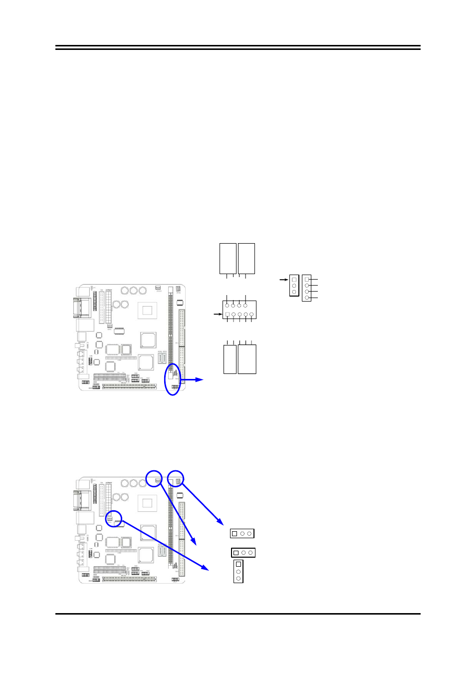
System Case Connections
HDL
E
D
R
E
SET
VC
C5
GND
VC
C
5
PW
R
LED
PW
R
B
T
N
PWR
B
T
N
PW
RLE
D
HDDLE
RS
TS
W
NC
GN
D
JW FP
Pin 1
SPEAK
SPKR
GND
NC
VCC5
PWRLED
Pin 1
(11) FAN Speed Headers (3-pin) : CPUFAN, SFAN1
These connectors support cooling fans of 350mA (4.2 Watts) or less, depending on the
fan manufacturer, the wire and plug may be different. The red wire should be positive,
while the black should be ground. Connect the fan’s plug to the board taking into
consideration the polarity of connector.
CPUFAN
1
3
SFAN1
1
3
SFAN2
1
3