MBM Corporation Paper Drill 200 single spindle User Manual
Page 5
5
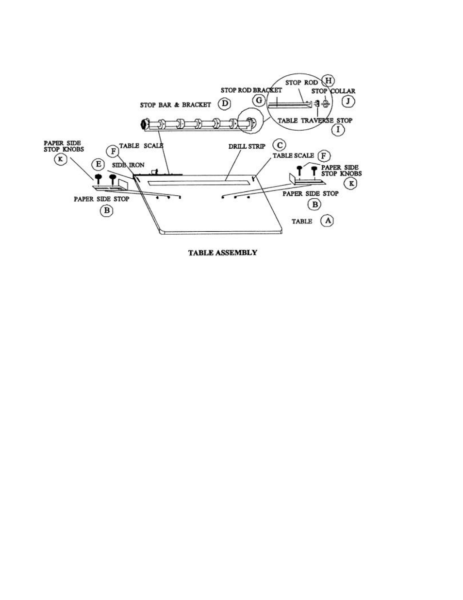
ILLUSTRATION #3
3. Install the Back Gauge Scale Assembly (Illustration No. 1) on the Table Assembly (Illustration No.
3). Grasp the Back Gauge Assembly by holding both ends with the scale facing you. Tilt the
assembly and slide the Back Gauge Scale Assembly under the Pressure Foot Assembly (Illustration
No. 2-F). Both the table clamp and back gauge clamp extend outside of the table and contact the table
side irons (B) (Illustration No. 3). Adjust to the position desired using the table scales (F) embedded
in the rear corners of the table to aid alignment. “0” is the center of the hollow drill.
4. Install the Table Stop Assembly (Illustration No. 4) by inserting the stop rod (C) through the hole in
the top of the Shroud Assembly and attach the lock knob (E). Screw the stop rod through the lock
knob and into the threaded hole in the center top of the Upright Assembly (F). To adjust the table
height, loosen the lock knob (B), depress the ha ndle until the correct table height is achieved
(explained later under Drill Bit Adjustments) and screw knob (B) into the Upright Assembly until the
stop rod meets resistance. Tighten the lock knob (E) against the Upright Assembly (F) to lock the
adjustment in place.