4 selecting cable, Installation – MMD Equipment 400S-6B1 User Manual
Page 22
3. Installation
3-8
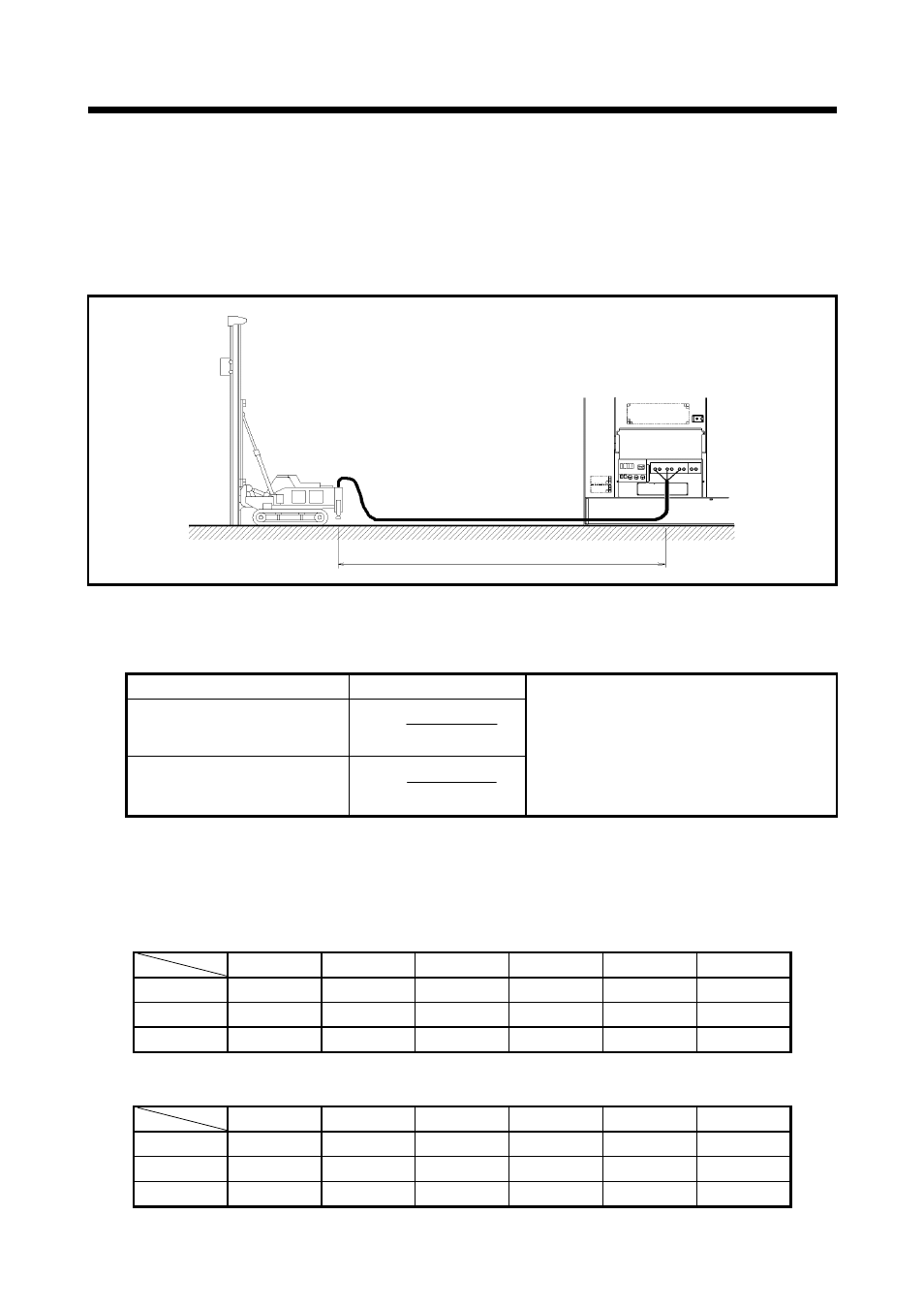
3.4 Selecting Cable
Select a cable with sufficient diameter by considering the permissible current on the cable and the
distance from the generator to the load.
If the current flowing to the load exceeds the permissible current of the cable, resultant
overheating may burn the cable. Similarly, if the cable is too small in thickness to the length, the
input voltage to the load will fall to cause the load input power to drop, as a result, the performance
of the machine cannot be displayed.
Simplified three-phase three-wire formula to seek voltage drop from cable length and working
current. Select such a cable length and thickness so that the voltage drop will remain less
than 5%.
Output system
Voltage drop
Three-phase 3-wire Type
Three-phase 4-wire Type
The following tables show the relations between the cabtyre cable length and the cable thickness
(nominal cross-sectional area) suited to the working current.
(Based on the condition that working voltage is 200 V, with voltage drop of 10V.)
Single-Conductor Cabtyre Cable
Unit:mm
2
Three-Conductor Cabtyre Cable
Unit:mm
2
50m 75m 100m 125m 150m 200m
400A 125 125 150 200 200 250
600A 200 200 200 250
150×2 200×2
1,000A
125×2 125×2 150×2 200×2 250×2 200×3
50m 75m 100m 125m 150m 200m
400A
60×2 60×2 60×2 80×2 100×2 125×2
600A
100×2 100×2 100×2 125×2 150×2 200×2
1,000A
150×3 150×3 150×3 150×3 200×3 200×3
Cable Length L(m)
Length
Current
Current
A080050
Length
Cable Thickness A (mm
2
)
Working
Current I (A)
e
:
Voltage drop(V)
e
:
Voltage drop between an outside
line or one line of each phase,
and a neutral line (V)
A
:
Cable thickness (mm
2
)
L
:
Cable length (m)
I
:
Working current (A)
e = 1,000×A
e =
17.8×L×I
1,000×A
’
’
30.8×L×I