Installation, Warning, H34dfn with logs only – Montigo H34DF User Manual
Page 14
H*34DF Indoor Gas Fireplace
Page 14
XG0146 - 150204
Installation
WARNING:
An inspection of the explosion relief flappers and door
MUST be made prior to lighting the fireplace. Faulty seal
on the door gasket and/or explosion ports will result in
products of combustion leaking into the living space and
may result in carbon monoxide poisoning.
Selection of components and details of venting layout should adhere
to the following guidelines:
Vent terminations must not be recessed in walls or siding.
For Heat Shield requirements, see Section 3-3-3 on page 16.
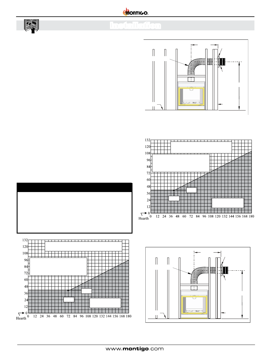
Once the proposed venting layout has been determined refer to Figure
14, 15, or 16 to ensure the layout is acceptable.
Notes Wall Mounted Terminations: TOP VENT
All measurements for vertical or horizontal runs are measured
from centre of the vent pipe.
Venting runs must fall within the limits set by the venting graph,
see Figure 14 or 15.
The Venting Graph
Measure the vertical height from the fireplace hearth to the centre of the
termination and the horizontal run from the fireplace flue collar to the
wall flange of the termination. Plot on the Venting Graph Figure 14 or
15 with an 'X'. If the 'X' falls on or above the top boundary of the shaded
area, the installation is acceptable.
Figure 15. H*34DF* Top Vent Venting Graph for wall mounted
terminations, See Figures 15a or 15b.
Figure 15a. Top Vented, wall mounted installation with 1 elbow (1 one
90° bend). The vent run must comply with Venting Graph for Top vent,
wall mounted terminations, Figure 15.
Figure 14a. H34DFN Top Vented, wall mounted installation with 1 elbow
(1 one 90° bend). The vent run must comply with Venting Graph for Top
vent, wall mounted terminations, Figure 14.
Wall mounted Terminations
The following details are some possible configurations for Wall mounted
terminations.
Figure 14. H34DFN Top Vent Venting Graph for wall mounted terminations,
See Figures 14a or 15b.
Heat
Shield
Termination
Hearth
Exterior
Wall
39” Min.
Flex section
40"
Max.
Heat
Shield
Termination
Hearth
Exterior
Wall
39” Min.
72” Max.
Flex section
72”
39”
Horizontal Run (in.)
Ve
rt
ical Height (in.
)
Unacceptable Vent run
within shaded area
If your installation does not fall within
the venting graph parameters, (non-
Shaded area) please contact a local
Montigo dealer for Power Venting options.
H34DFN with LOGS ONLY
40”
39”
Horizontal Run (in.)
Ve
rt
ical Height (in.
)
Unacceptable Vent run
within shaded area
If your installation does not fall within
the venting graph parameters, (non-
Shaded area) please contact a local
Montigo dealer for Power Venting Options.
All Other Models including
H34DF with Rock Option
Section 3-3-1: Venting Layout: Wall mounted termination