ONICON D-100 Dualnet User Manual
Page 9
11451 Belcher Road South, Largo, FL 33773 • USA • Tel +1 (727) 447-6140 • Fax (727) 442-5699 • [email protected]
D-100 Dual Network Interface Installation Guide 07/14 - 1015
Page 9
1.5.3 Optional Network Interface With Isolated Digital Pulse Input (Di3)
The D-100 Flow Display can be provided with an auxiliary pulse input for totalizing
pulse outputs from external devices such as water or gas meters. Pulses are accumulated
in an internal register. The totalized value is shown on the display and is available on
the network. This register can be zeroed via the network. The maximum register total is
9,999,999. The register will rollover to zero when this value is exceeded.
If the auxiliary pulse input option was ordered at the same time the Display was ordered,
it will arrive fully configured and ready to use. If it was ordered after the Display was
delivered and is being installed as a field upgrade, it may be necessary to configure the
pulse input. The information required to configure the input is provided below and on the
following pages:
The input pulse must meet the following criteria:
1.
Frequency input range, 50 Hz maximum
2.
10 millisecond minimum pulse duration
Input Pulse Definition:
In order to configure the communications card auxiliary pulse input, you must first
determine which type of pulse your meter produces. The allowable types of input pulses
are described on the following pages. Based on the type of pulse, set the selector switch
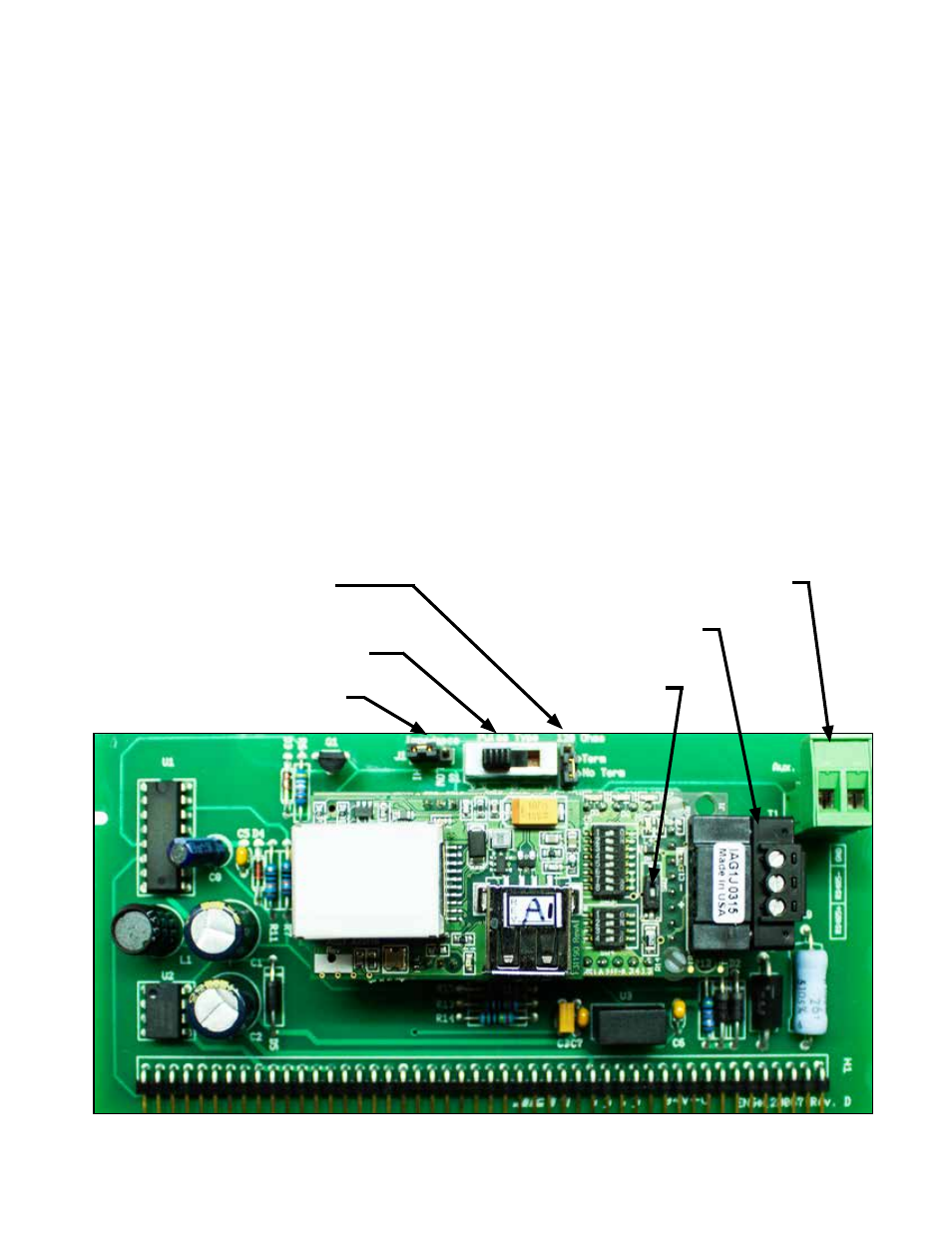
(S1) on the communications circuit board (Fig. 1) to the correct setting.
Fig. 1
120 ohm Jumper Selectable
Termination Resistor
Pulse Type Selector Switch (S1)
Input Impedance Jumper (J1)
Aux Pulse Input (Di3) Connector (T2)
RS485 Connector (T1A)
Unused
Leave OFF