4 wiring – OnLine Power Signal Saver IPC User Manual
Page 18
6002-1842 Rev A ECO# 8881
8
1.4
WIRING:
Before wiring the system determine size of the load:
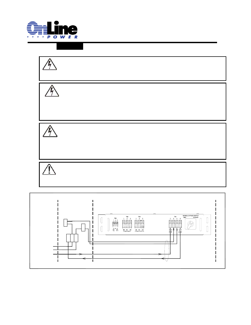
Load/Input Wiring:
Figure 1.4
G BUS
332 CABINET
LINE
GND
LINE
UTILITY
NEUTRAL
AC OUTPUT
EXTERNAL CABINET
UTILITY LINE IN
N BUS
G
L
N
NEU
MBS/PTR
GND
7060-1091-01
HARNESS
DANGER: If this is a new traffic signal installation with Utility AC power going directly to UPS, make
sure the upstream circuit breaker feeding the Utility Power is OFF before beginning wiring. If this is
addition of a UPS to an existing traffic signal cabinet, DO NOT terminate the power cable from the
signal cabinet to the UPS at the signal cabinet end until the final step after all other connections have
been completed. This will minimize the length of time the traffic signals must be off for final power
connection.
DANGER: There are many different ways that the Utility AC can be wired into the traffic signal
cabinet. The intent of this manual is only to explain proper connection of utility AC at the UPS end of
the cable. How the Utility AC is routed from the service entrance or through the traffic signal cabinet
(hereafter referred to as the “power source”) to the UPS shall be determined by a licensed electrician
in accordance with local electrical codes.
DANGER: The utility input power line must have circuit breaker or fuse protection as per the local
electrical code. It is referred as “Upstream Circuit Breaker” in this manual.
TIP: The suggested method of wiring utility AC to the UPS from the traffic signal cabinet is to
connect the UPS at the traffic cabinet after the main cabinet breaker and surge suppressor so that
the UPS is also protected by the cabinet surge suppressor.