Ò³ãæ 19 – Onwa Marine Electronics KR-12X8 User Manual
Page 19
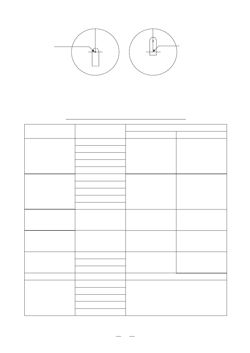
Radar antenna
position is at
center of display
Conning position is at
center of display
ANT position
CCRP position
Range and bearing are measured and graphics are drawn according to reference
position as in the table below.
Marks, measurements and reference point
Category
Item
Reference point
CCRP
Antenna position
Range and bearing
measurement
EBL
VRM
Cursor
PI line
Range ring
Range and bearing
measured from CCRP
Range and bearing
measured from antenna
position
Heading line
Stern mark
Beam line
Own ship vector
Own ship track
Drawn from CCRP
Drawn from antenna
position
Graphics
Bearing cursor
Drawn with CCRP at
center
Drawn with antenna
position at center
Course, speed
Calculated with CCRP
at center
Calculated with antenna
position at center
CPA,TCPA
Calculated with CCRP
at center
Calculated with antenna
position at center
BCR, BCT
Calculated from bow position
Own ship data
Heading
Speed
Course over ground
Speed
over ground
Own L/L
Data from sensor, regardless of reference
point selected
12