8 electrical wiring, 1 general information, 2 connecting the indoor unit – REMKO RVT 263 DC User Manual
Page 39: 8electrical wiring
8
Electrical wiring
8.1 General Information
A protected power supply cable is to be connected
to the outdoor unit and a 4-wire control line to the
indoor unit respectively.
DANGER!
All electrical installation work is to be per-
formed by specialist companies. Disconnect
the power supply when connecting the elec-
trical terminals.
WARNING!
All electric lines are in accordance VDE regula-
tions to dimension and to lay.
NOTICE!
The electrical connection for the units must be
made at a separate feedpoint with a residual
current device in accordance with local regula-
tions and should be laid out by an electrician.
We recommend using shielded wires for the
control lines.
Check all plugged and clamped terminals to
verify that they are seated correctly and make
permanent contact. Tighten as required.
8.2 Connecting the indoor unit
n
We recommend installing a main / repair switch
on the building close to the indoor unit. This is
the responsibility of the customer.
n
The terminal blocks for making the connections
are located at the rear of the unit. When the
unit is installed, measurements can be made
from the front by removing the cover.
n
If an optional condensate pump is used in con-
junction with the unit, it may be necessary to
install an additional relay with a higher contact
rating after the switch-off contact on the pump
to switch off the compressor.
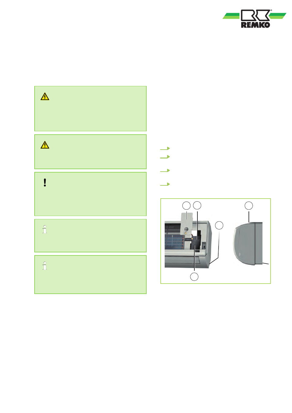
Make the connection as follows:
1.
Open the air inlet grill.
2.
Remove the covers on the right-hand side
3.
Connect the customer-laid control line to the
4.
Re-assemble the unit.
2
1
4
3
1
Fig. 46: Connecting the indoor unit
1: Cover
2: Strain relief
3: Terminal block for control line
4: Control line from outdoor unit
39