Ab c – REMKO RVT 263 DC User Manual
Page 41
Advertising
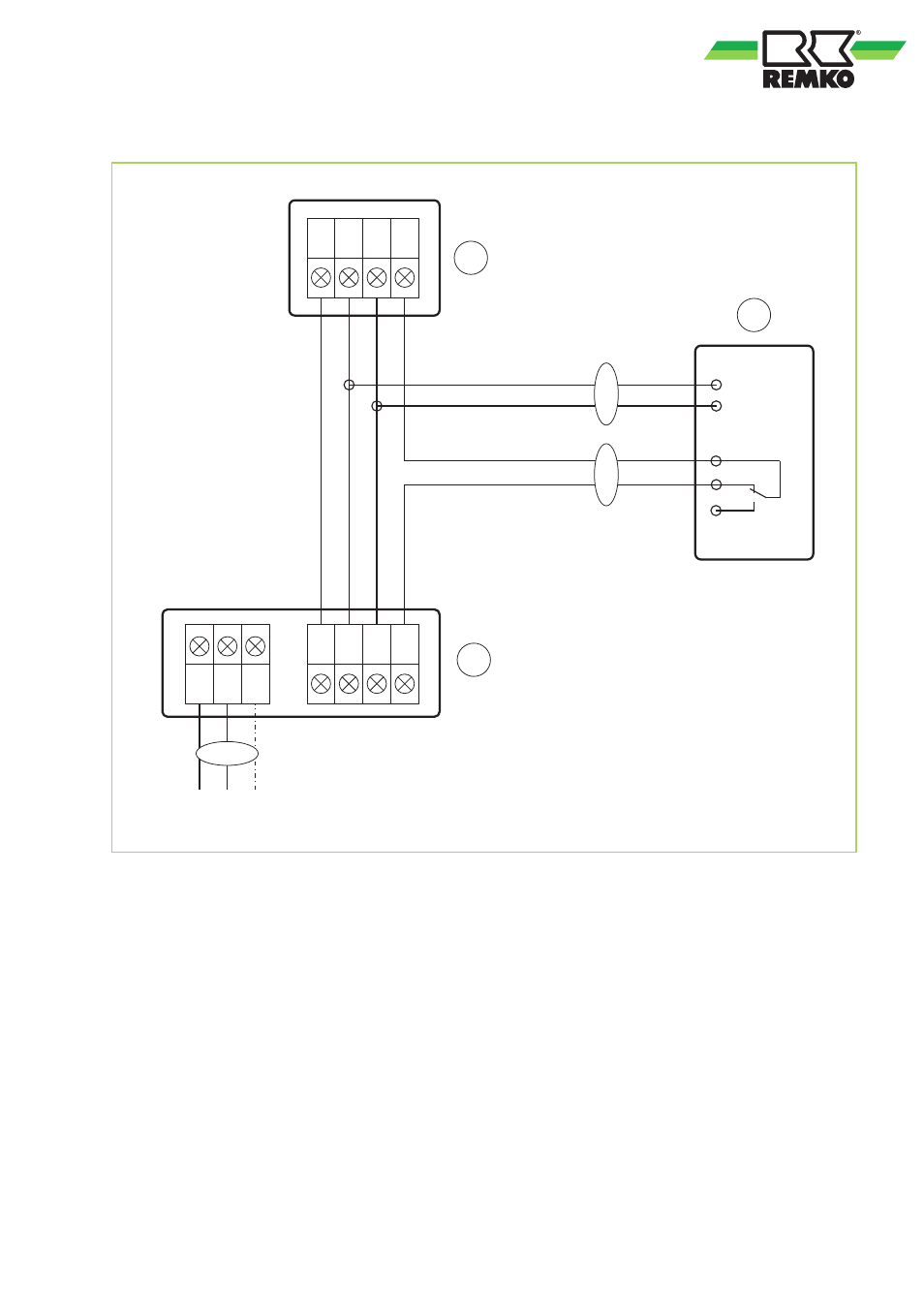
Connection of optional condensate pump KP 6 / KP 8
L N PE
L
N PE
L(1) 1 2(N) S
L(1) 1 2(N) S
L
N
WH
BK
A
B
C
1
2
3
Fig. 49: Electrical wiring diagram
A:
Outdoor unit
B:
Indoor unit
C:
Condensate pump KP 6 / KP 8
1:
Power supply
2:
Condensate pump supply
3:
Condensate pump fault contact
BK: Black
WH: white
41
Advertising
This manual is related to the following products: