For the installer: tubing installation – Scotsman RS160 User Manual
Page 4
FOR THE INSTALLER: Tubing Installation
1. Locate the dispenser on the counter. Allow
vertical clearance above unit for the removal of the
cover, and for pouring ice into the hopper.
Note: If installing an ice cube machine on top,
check for proper total cabinet clearance, including
adapter kit.
The syrup and carbonated water connections need
to be made at the cold plate’s stub lines. The cold
plate stub lines are behind the splash panel.
Tubing routing to the cold plate is from either the
back of the unit, or through openings in the base.
A plumbing circuit schematic diagram is on the
back of the cabinet, refer to it for cold plate
connections.
2. Plan the routing of the tubing (drain and soda).
If the tubing will pass through the base, a hole
in the counter top must be made prior to
sealing the unit to the counter.
The tubing may also be routed through the back.
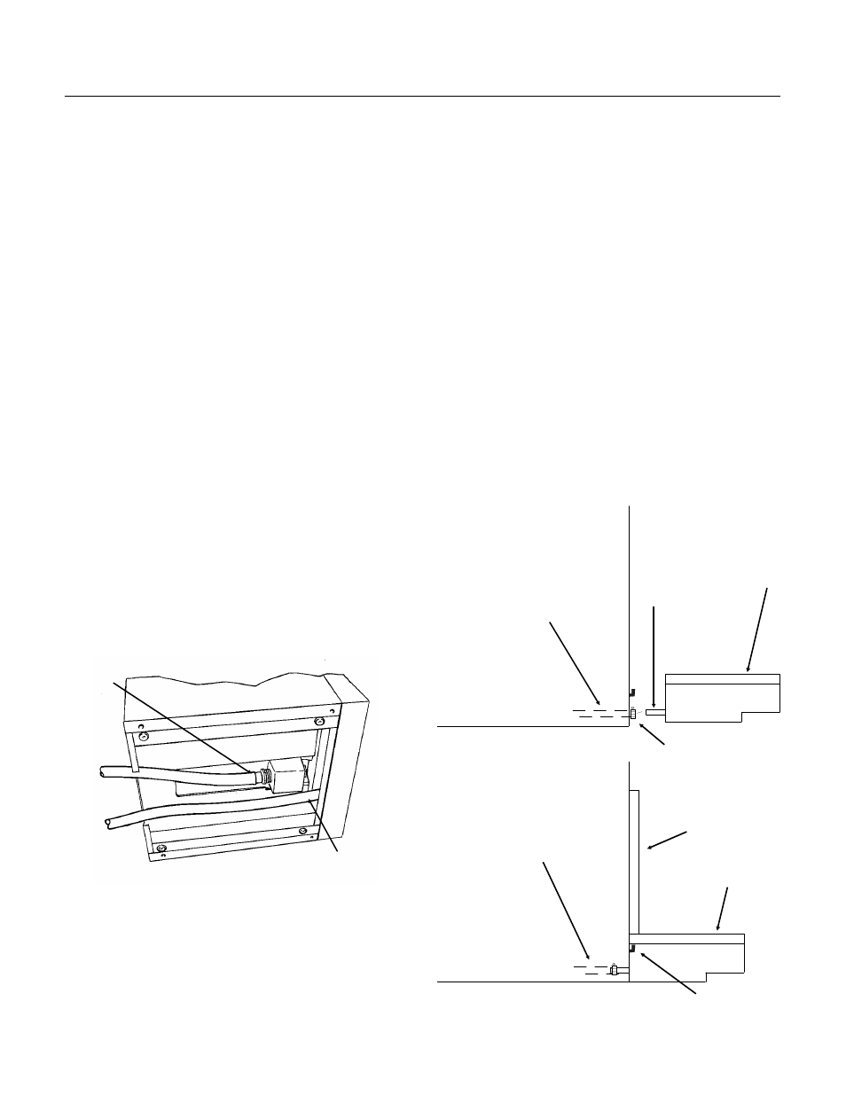
3. Connect the drain system. There are two drains
to connect: The sink (or drip tray) drain and the
cold plate drain. They must be routed separately.
The tubes may drain the unit through the back or
through the openings in the base.
The cold plate drain tube is the one with the foam
insulation on it. Tilt or lift the unit to expose the
bottom of the dispenser.
Connect the threaded drain fitting (packed loose in
the hopper) to the cold plate drain connection.
Connect the cold plate drain tube to this fitting,
route the hose to the building drain.
Install the sink drain after the machine has been
set in place.
Drip Tray/Grill
1. Remove splash panel from unit.
2. Connect the sink drain hose to the sink drain
fitting and secure it with a hose clamp. Route the
tube to the building drain. Follow all local plumbing
codes.
4. Hang the drip tray onto the metal tabs on the
base of the unit.
5. Replace the splash panel.
Note: If the cabinet has been sealed to the
countertop, add sealant around the sink and
counter top to provide a seal with a radius of 1/2".
Follow the sealant manufacturer’s instructions on
the package for working with the sealant, and
cleaning up.
SIDE VIEW OF DRIP TRAY INSTALLATION
DRAIN TUBING
DRAIN
FITTING
DRIP TRAY
DRAIN TUBING
DRIP TRAY
HOSE
CLAMP
SPLASH
PANEL
MOUNTING TABS
Cold Plate
Drain
Connection
Bottom View of
Dispenser
Sink Drain Connection
RS160 and RS220
June 1995
Page 4