5 connections – Sim2 HT200 DMF User Manual
Page 10
10
5 CONNECTIONS
This input is suitable for equipment fitted with a S-Video output
to give improved picture performance (S-VIDEO/S-VHS)
Connection is made via a 4-pin mini-DIN
(Fig. 20)
.
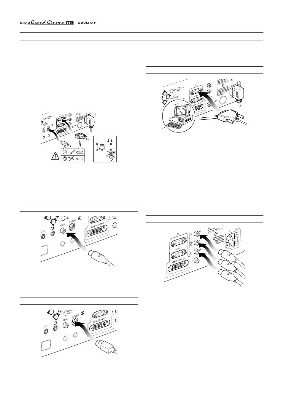
VGA INPUT
Fig. 21
Personal Computers, Video Processors (scalers) and Video
Game consoles can be connected to the projector via the HDB
15-Pin (VGA) terminal. Ensure the output of equipment
connected is RGB with one of the following synchronisation
options: separate H/V Sync, H+V Composite Sync, (RGsB)
composite sync on the green signal
(Fig. 21)
.
This input accepts a Horizontal Scan Frequency of between 15-
80 kHz and a Vertical frequency of between 40-100 Hz. Com-
puter Resolutions of VGA, SVGA, XGA, SXGA and UXGA can
be displayed.
The true native resolution of the projector is SVGA (800 x 600)
in 4:3 mode and WVGA (848x480) in 16:9 mode.
RGB/YC
R
C
B
INPUT
RG
S
B - Y
S
C
R
C
B
COMPONENT
VIDEO
Fig. 22
This input is suitable for a RGB video signal, or for a Component
(YCrCb) type, with composite synchronisation on the green signal
(RGsB) or on the luminance (Y) signal (YsCrCb) through a cable
with RCA/Phono type connector
(Fig. 22)
.
Only horizontal scanning frequencies of 15 kHz (standard video
resolution) or 32 kHz (high definition video, with progressive
scanning) can be applied to this input.
To obtain the best performance from your projector, we
recommend the use of good quality “video cables” to the various
signal sources (75 ohm Impedance).
Poor quality cables will cause inferior picture performance.
For optimum connectivity we recommend you follow these simple
steps:
- With exception of coaxial RCA/Phono type connectors,
always double-check that the plug is inserted the correct way
round to avoid damaging the plugs or the sockets on the
projector
(Fig. 18)
.
75
Fig. 18
- Remove cables by the plug and do not pull on the cable itself.
- Avoid tangled cables.
- Position the cables carefully to avoid a trip hazard - especially
in low light areas.
COMPOSITE VIDEO INPUT
CVBS
COMPOSITE VIDEO
Fig. 19
This input is suitable for a “Composite Video CVBS” via a cable
with an RCA/Phono connector
(Fig. 19)
.
S-VIDEO INPUT
S-VIDEO
Fig. 20