English – Sim2 HT200 DMF User Manual
Page 11
11
ENGLISH
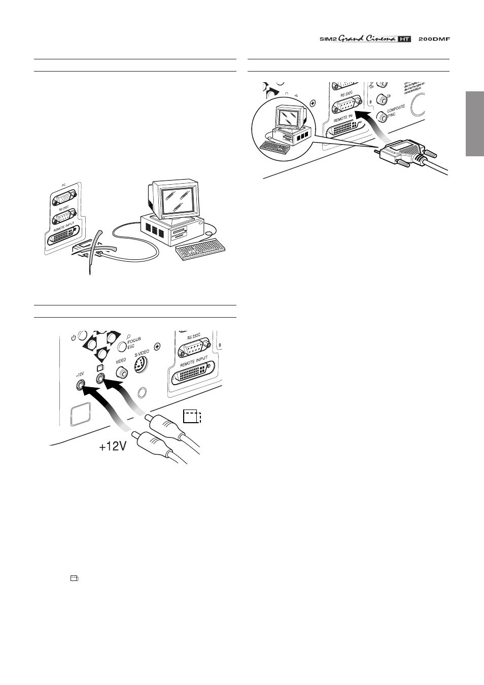
REMOTE INPUT INTERFACE CONNECTING CABLE
With a special cable (optional), it is possible to connect the Re-
mote Input Interface (optional) to the projector.
Connect/disconnect the special Remote Input Interface cable
only when the projector is switched off and disconnected from
the mains (switch in position O).
CAUTION: This is not a VESA “Plug & Display” connector.
Never connect a computer to this socket as the projector
and the computer may be damaged
(Fig. 23).
Fig. 23
MOTORISED PROJECTION SCREEN OUTPUT
Fig. 24
The projector is equipped with two outputs (Voltage: 12 Vdc) for
motorised projection screen and screen masking systems. These
12V outputs should be connected to the appropriate screen
interface provided by the screen manufacturer
(Fig. 24)
.
The +12V output is activated when the projector is switched on
(green LED on) and is de-activated when the projector is in stand-
by mode (red LED on).
The output
can be used to control a screen masking system;
its output can be set with the “Screen control” adjustment in the
“Aspect” menu.
This output allows reduction in the area of a 16:9 screen, into a
4:3 format, by activating a screen masking system (refer to
screen manufacturer for further information).
RS232 INTERFACE CONNECTOR
RS 232
Fig. 25
It is possible to control the projector through a personal compu-
ter. First, load the appropriate projector control software onto
your PC, then simply connect this input to a cable from your
PC’s RS232 serial port
(Fig. 25)
.