SONOSAX SX-62R Quick_Start User Manual
Page 8
SONOSAX SX62R
Quick Start Guide
Page 8 of 34
4.2
MIC/LINE INPUT CONFIGURATIONS
From the main menu, enter the inputs configuration page by touching the [INPUTS] key. A new screen is
posted, displaying the actual configuration of the input channels as illustrated below.
Each input channels of the analogue mixer can be configured individually; active (enabled) functions are high-
lighted in blue.
Touching a region (in a square) calls a specific sub menu to configure the channel's parameters.
Power On / Off
48V Phantom
Phase reversal
Toggle Pre or Post
Fader routing to the
recorder
Limiters Threshold
Returns to previous
Menu
Fader (Volume Control)
Routing to the Mix Busses
Assignment to the mix busses
Direct access to channels
1 & 2
3 & 4
5 & 6
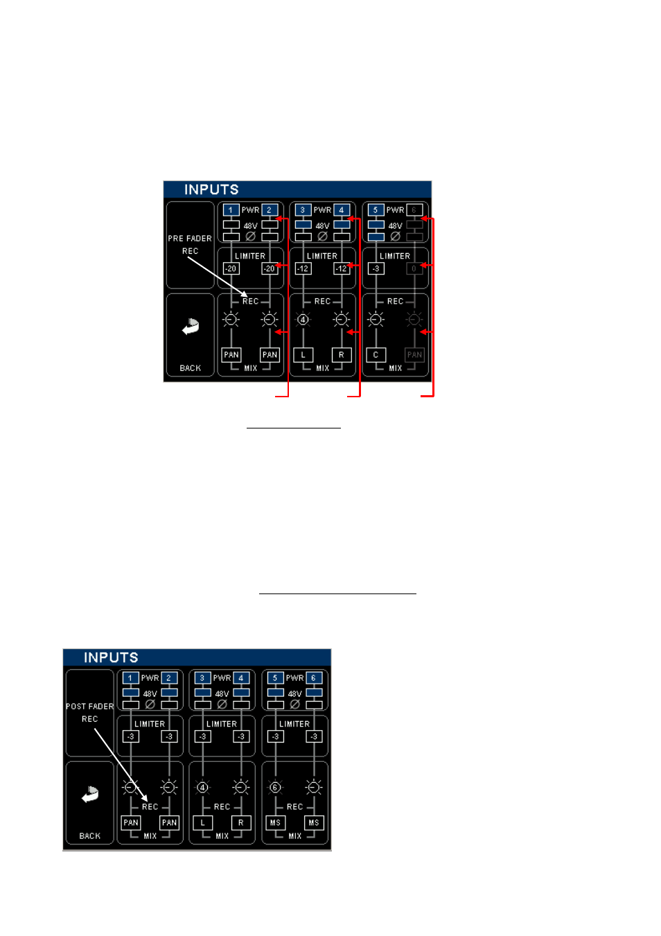
The above example shows a typical "mixer configuration" where the final mixing is done on location and the
input channels are recorded "Pre Fader" for back-up purposes:
- Input channels 1 to 5 are powered On; input channel 6 is powered Off to save on batteries
- Input channels 3 to 5 have the 48V phantom are turned On
- The Polarity of Input channels 5 is reversed.
- The Threshold level of each Limiter is indicated individually.
- All input channels are sent PRE Fader to the recorder [REC]
- Input channels 1 & 2 are assigned to the Mix Bus [MIX] through the [PAN] pot.
- Input channel 3 is assigned to the Left mix bus; channel 4 to the Right mix bus, [PAN] is disabled
- Faders of channels 3 & 4 are linked as stereo pair, Fader 4 controlling channels 3 & 4
- Input channels 5 is assigned in the centre [C]; equally to the Left and Right mix busses, the [PAN] is disabled
The following example shows a typical "Recorder setting with rough mix"; the channels are sent Post Fader to
the Recorder, the Faders are used to control the recording level to optimize the S/N ratio and the resolution
over the entire dynamics range on the recorded tracks. In this case the analogue mix is recorded as a rough
mix only for editing purposes.
Input channels 1 to 6 are powered ON
48V Phantom is enabled on each input
No polarity reversal is active
The Limiter Threshold is set to -3dBFS to make use of
the full dynamic range. They protect the A/D Converter
leaving only 3dB of Headroom
Channels 1&2 are individually controlled by their own
fader
Channels 3&4 are linked as stereo pair , controlled by
fader 4
Channels 5& 6 are a M/S pair, controlled by fader 6, the
M/S signal is decoded
All channels are assigned on the mix busses