Connection - catlinc receiver, Connecting the receiver – SP Controls CatLinc User Manual
Page 12
CONNECTING THE TRANSMITTER Cont.’d
CatLinc HD
1) Attach the 3 RCA connectors labeled SOURCE on the Transmitter to the
Composite Video output (e.g., Y,P
B
,P
R
) port on the source device. Standard
wiring convention is: Green RCA to Y, Red to Pr/U, Blue to PB/V.
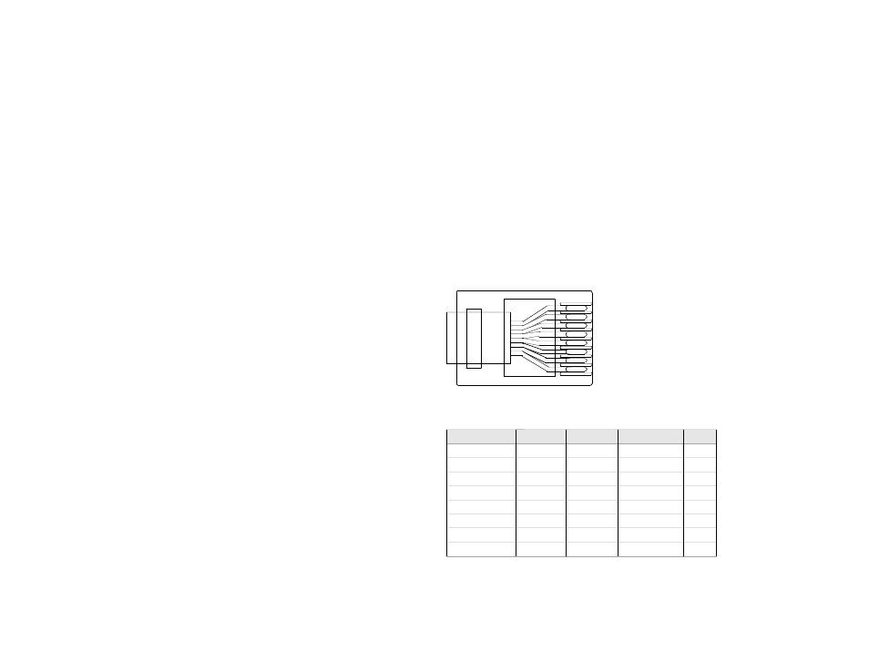
2) Attach one end of the CAT5 cable into the RJ-45 jack labeled CAT5 on
the Transmitter.
3) Mount the device anywhere with the Velcro strips provided.
CONNECTING THE RECEIVER
1) Attach the other end of the CAT5 cable to the CatLinc Receiver in the RJ-
45 jack labeled CAT5.
2) Attach the 15 pin HD D-sub, mini-DIN, or RCA connectors labeled
DESTINATION (illustrated with an icon showing a monitor and a
projector) on the CatLinc Receiver to the appropriate input port on the moni-
tor or video projector.
3) For the CatLinc VGA/VGA-L the 9-Volt DC Power Supply may be
attached at either the Transmitter or the Receiver to the jack labeled DC
Power In.
For the CatLinc VID, CatLinc S-VID, or CatLinc HD, if your cable length
exceeds 110m (350ft), the CatLinc must be powered at both the Transmitter
and Receiver ends.
4) Once the devices are connected and power is applied to one or more
units, the you should see the POWER Led illuminate on both the Transmitter
and Receiver.
For the CatLinc VGA/VGA-L, when the Transmitter and Receiver are con-
nected and the system is powered, you should see the SIGNAL LED illumi-
nate.
NOTE: It is normal for the Transmitter and Receiver units to become warm
during operation.
10