Cat5 wiring, Figure 7 - tia-eia t568b wiring (top view), Table 2 - rj-45 pinouts – SP Controls CatLinc User Manual
Page 9
-
-
CAT5 WIRING
You must supply a standard 4-Twisted Pair cable terminated with two RJ-45
connectors (CAT5, CAT5e, or CAT6) to connect the Transmitter to the
Receiver. For easiest use it is highly recommended that you use pretermi-
nated CAT5 cable. If you terminate your own CAT5 cable, we recommend
use of the TIA-EIA T568B wiring standard (Cf. Figure 2).
In either case we strongly suggest the use of shielded twisted pair (STP) or
foil shielded twisted pair (FTP) cable over unshielded twisted pair cable
(UTP).
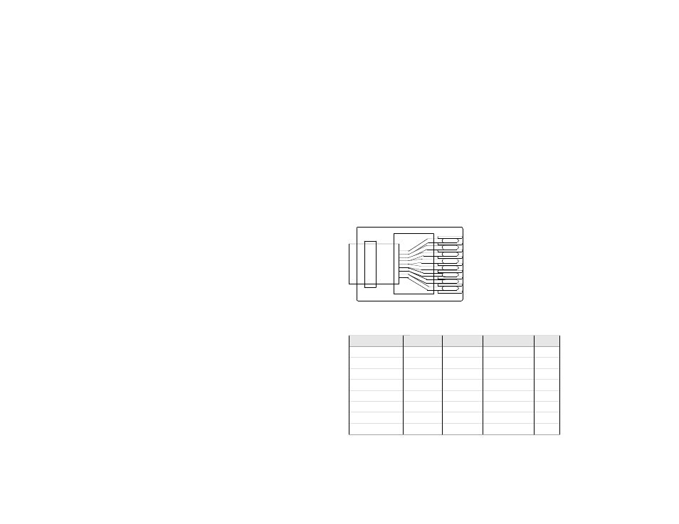
Figure 7 shows the preferred RJ-45 pinout. Make sure that you have the
proper tools and test equipment necessary to test that the resulting cable
meets the CAT5 standard. Table 2 indicates the RJ-45 pinouts for the vari-
ous CatLinc models.
WARNING: Failure to completely crimp down the RJ-45 connectors can
damage the CatLinc.
Figure 7 - TIA-EIA T568B Wiring (top view)
White Base/Orange Stripe
Orange Base/White Stripe
White Base/Green Stripe
Blue Base/White Stripe
White Base/Blue Stripe
Green Base/White Stripe
White Base/Brown Stripe
Brown Base/White Stripe
Table 2 - RJ-45 Pinouts
RJ-45
VGA/VGA-L
VID
S-VID
HD
1) White/Orange
Red
VID
Y (Luminance)
Y
2) Orange/White
Red
VID
Y (Luminance)
Y
3) White/Green
Blue
Audio Right
unused
Pb
6) Green/White
Blue
Audio Right
unused
Pb
4) Blue/White
Green
Audio Left
C (Chrominance)
Pr
5) White/Blue
Green
Audio Left
C (Chrominance)
Pr
7) White/Brown
+9VDC
+9VDC
+9VDC
+9VDC
8) Brown/White
GND
GND
GND
GND
7