Typical assembly overview (ets 40ft shown) – Space Ray ETS Series User Manual
Page 19
Form 43343300
-18-
May 2013
8.2)
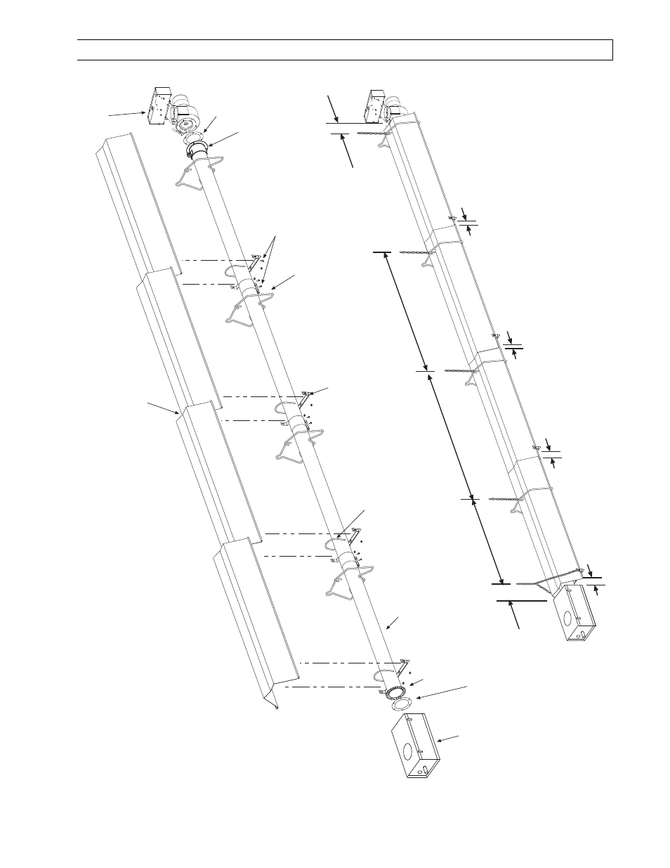
HEATER ASSEMBLY / JOINING OF TUBE SECTIONS
T
ypical
Assembly Overview
(ETS 40FT
Shown)
4"OD x 10Ft. See sections 7.0 & 7.1 for required tubes.
T
ube Support Bracket
U-Bolt Clamp & 5/16" Hex Nut
s
T
ube Flange
12 Radial Hole for 40-200M BTU unit
s only
6 Hole for 225-250M BTU unit
s only
Wire Hanger
Gasket
Control Box
Draf
t Inducer
Assembly
Gasket
Maximum 6 dist
ance
from control box to the tube support/hanger bracket.
8
- 9
¼
8
- 10
8
- 10
Not Less Than 10
#10 Self-Drill Screws (T
ypical all tube support
s
and tube couplings.)
T
ypical
Overlap
Draf
t Inducer
Flange
5 hanging point
s to be used for suspension.
There must be two hanging point
s on the first
tube and one on each of the other tubes
3 (control box to reflector)
2 overlap
1 overlap
1 overlap