Space Ray ETS Series User Manual
Page 25
Form 43343300
-24-
May 2013
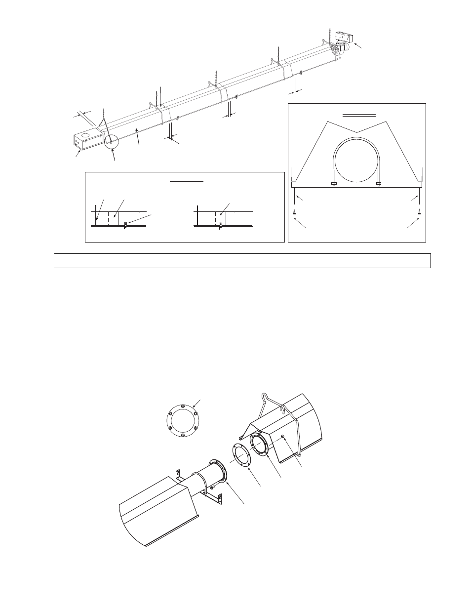
2 OVERLAP
1 OVERLAP
1 OVERLAP
DETAIL A
REFLECTOR
40 FT SYSTEM SHOWN
3
(control box to reflector)
DRAFT
INDUCER
CONTROL
BOX
REFLECTOR
OVERLAP
(offset from tube
support/hanger brackets)
CORRECT INSTALLATION
Wire
Hanger
Tube
Support/Hanger
Bracket
REFLECTOR
OVERLAP
(positioned over tube
support/hanger brackets)
INCORRECT INSTALLATION
DETAIL B
DETAIL B
The reflector overlap
must be able to slide at
this joint for expansion
of the heater.
Fasten screws to tube support/hanger
bracket and reflector (Typical all tube
support/hanger brackets)
#10 x 1/2 SHEET METAL SCREWS
(QTY - 2)
DETAIL A
10.3)
JOINING OF FLANGED TUBE SECTIONS – ETS/ETU 225-250 SERIES
The control box must be attached to a 6-hole flange on the 10 ft. Starting Tube Section (this tube section has a
6-hole flange at both ends of the tube). The other 6-hole flange must be connected to the 6-hole flange of the
Secondary Tube Section for ETS/ETU225-250 models. The ¼-20 screws, locknuts and flange gasket required to
attach these two tube sections together are included in the Body Fastener Kit of the Starting Body Package. Join
the two tube sections together as indicated below:
1.
Join the tube flanges of the tube sections together with the gasket in between. Loosely attach the heater
tube sections together with the ¼-20 screws and locknuts provided. DO NOT
DO NOT
DO NOT
DO NOT fully tighten the screws and
locknuts yet!
2.
Tighten the screws and locknuts using the sequence shown. The screws and locknuts should be tightened a
little bit at a time (the same way you would secure the lug nuts to a car wheel).
3.
The remaining tube section joints are coupled with a compression coupling. Refer to the previous
instructions for the installation of these couplings.
Tube Flange
(with 6 holes)
Tube Flange
(with 6 holes)
Gasket
Tube Flange
(tightening sequence)
10FT Starting
Body Section
10FT Secondary
Body Section
1/4-20 Screw & Locknut
(QTY-6 per flange)
1
3
5
4
2
6