0) attaching control box assembly – Space Ray ETS Series User Manual
Page 28
Form 43343300
May 2013
-27-
11.0)
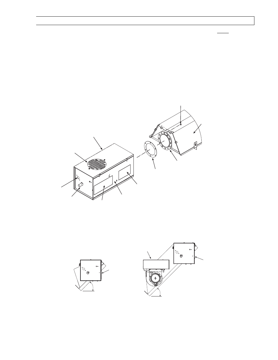
ATTACHING CONTROL BOX ASSEMBLY
1.
Attach the control box and gasket to end of tube flange and secure with 1/4-20 locknuts. NOTE:
NOTE:
NOTE:
NOTE: The control
The control
The control
The control
box must b
box must b
box must b
box must be mounted to a 10 ft. aluminized steel
e mounted to a 10 ft. aluminized steel
e mounted to a 10 ft. aluminized steel
e mounted to a 10 ft. aluminized steel tube section
tube section
tube section
tube section for 40
for 40
for 40
for 40----200 MBtu/hr models, or to a 10 ft.
200 MBtu/hr models, or to a 10 ft.
200 MBtu/hr models, or to a 10 ft.
200 MBtu/hr models, or to a 10 ft.
Alumi
Alumi
Alumi
Alumi----Therm steel
Therm steel
Therm steel
Therm steel tube section
tube section
tube section
tube section for 225
for 225
for 225
for 225----250 MBtu/hr models, regardless of configuration used.
250 MBtu/hr models, regardless of configuration used.
250 MBtu/hr models, regardless of configuration used.
250 MBtu/hr models, regardless of configuration used. Failure to
Failure to
Failure to
Failure to
attach the control box to the flange end as indicated abov
attach the control box to the flange end as indicated abov
attach the control box to the flange end as indicated abov
attach the control box to the flange end as indicated above will void the manufacturer’s warranty.
e will void the manufacturer’s warranty.
e will void the manufacturer’s warranty.
e will void the manufacturer’s warranty.
2.
A 3/8" connector is located on the left side of the control cabinet to provide strain relief for field wiring to
the draft inducer junction box (refer to Section 16.0) on Electrical Connections and Connection Wiring
Diagram for wiring between the control box and the draft inducer.)
3.
Assemble the end reflector (optional on ETS/ETU series) flush with the end of the main reflector. Secure by
sliding speed clips onto the reflector edges. Evenly space the speed clips on the sides (one each side) and
top (two required) of the reflectors to provide a snug fit. Leave a 3" space between the end reflector and the
control box assembly.
4.
The control box must be mounted with the perforated fresh air plate on top, facing the ceiling.
Tube Flange
12 Radial Hole for 40-200M BTU units only
6 Hole for 225-250M BTU units only
MPT Gas
Pipe Connection
Reflector
1/4-20 Locknut
(QTY-3 per flange)
Tube Flange
Gasket
3/8 Connector
(24V wire leads from
draft inducer to
L1 and L2 of the
control box terminal block)
Control Box
Perforated
Fresh Air Plate
Burner
Sight Glass
Nameplate/
Rating Label
Clearances to
Combustibles
Label
Access
Panel
Note: The wiring connection
diagram is located on the inside
access panel and inside the
junction box panel.
5.
The heater can be mounted horizontally
horizontally
horizontally
horizontally or at an angle of up to 45 degrees
45 degrees
45 degrees
45 degrees maximum from horizontal.
When angle mounting, the control box
control box
control box
control box must be positioned upright
upright
upright
upright as shown below. Failure to install the control
Failure to install the control
Failure to install the control
Failure to install the control
box in an UPRIGHT
box in an UPRIGHT
box in an UPRIGHT
box in an UPRIGHT position will VOID the manufacturer’s warranty
position will VOID the manufacturer’s warranty
position will VOID the manufacturer’s warranty
position will VOID the manufacturer’s warranty.... For additional instructions see Section 13.0)
for multiple hanging and draft inducer positions.
Angle Mounting
Straight Tube Heaters
Angle Mounting
U-Tube Heaters
Draft
Inducer
Control
Box
Upright Position
Junction Box
Control
Box
Upright Position
6.
Control box
Control box
Control box
Control box can be installed in lower side when angle mounting. Please ensure that there is adequate
clearance to open the control box
control box
control box
control box access panel for servicing the heater.