2) adding reflectors – Space Ray ETS Series User Manual
Page 24
Form 43343300
May 2013
-23-
5.
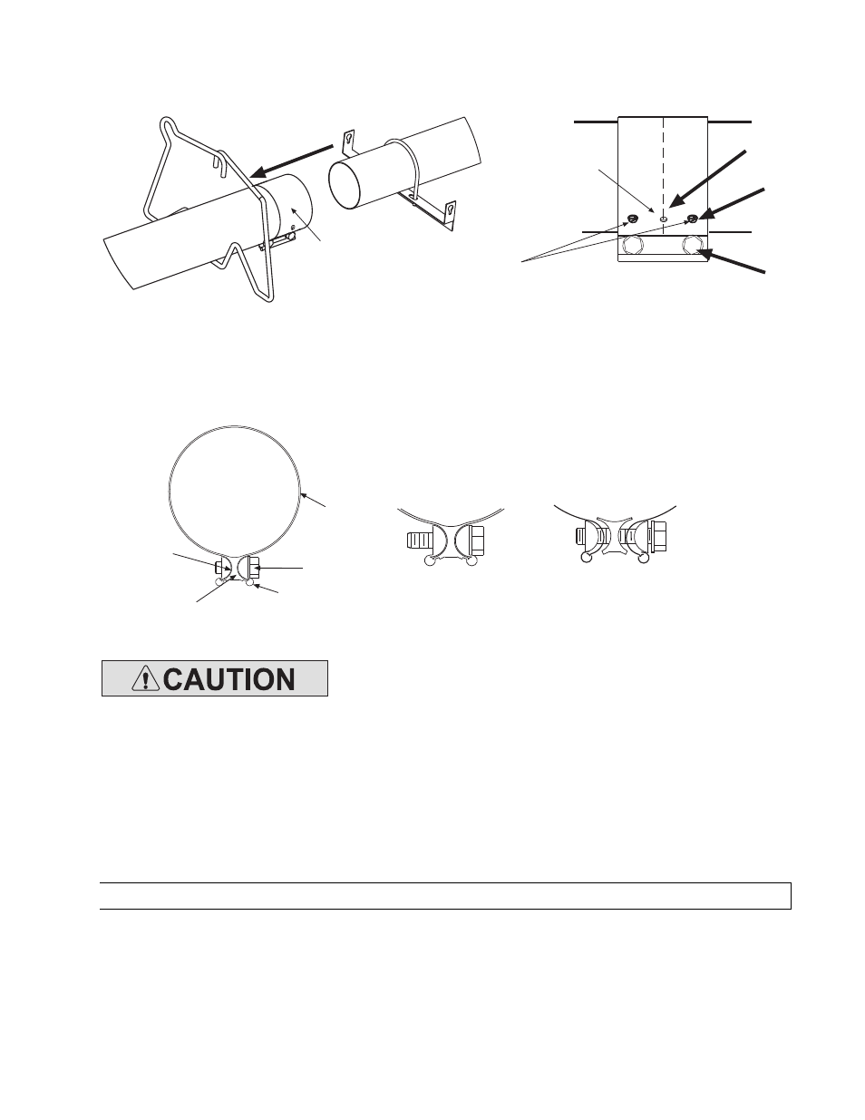
Make sure both tube ends are butted together.
6.
Finish tightening both bolts to 40-60 ft.lbs. torque to ensure a complete seal.
7.
Use the two Self-drilling screws through the pre-punched holes to secure the tubes in the coupling.
Tube
Coupling
Center both
tubes with hole
#10 Self-Drilling
Screws
(QTY 2)
4
5
7
6
8.
Check to ensure that the hardware is completely closed and the band is seated on the reaction block and
interference pins as illustrated above.
9.
Once all the heater tube sections are attached, make sure that the heater system is level. If it is not, slight
adjustments can be made using the turnbuckles. (See Section 9.0)
INCORRECT
INSTALLATION
CORRECT
INSTALLATION
Force
Bars
Reaction
Block
Interference
Pins
Bolt
Band
Important:
Important:
Important:
Important: NEVER
NEVER
NEVER
NEVER rrrreuse a coupling
euse a coupling
euse a coupling
euse a coupling.... Always install a new coupling only and
Always install a new coupling only and
Always install a new coupling only and
Always install a new coupling only and
torque as per instructions above and the diagrams above.
torque as per instructions above and the diagrams above.
torque as per instructions above and the diagrams above.
torque as per instructions above and the diagrams above.
10.2)
ADDING REFLECTORS
1.
Slide the reflectors on the tube support/hanger brackets and through the wire hangers.
2.
The tube at the coupling joints must be covered. Slide the reflectors together and provide an overlap of two
(2”) inches for the first reflector overlap after the control unit. All remaining reflector overlaps will be
approximately one (1”) inch. This will allow for the natural expansion and contraction of the heater when in
operation. Note: The heaters can expand and
Note: The heaters can expand and
Note: The heaters can expand and
Note: The heaters can expand and contract up to 1
contract up to 1
contract up to 1
contract up to 1----3/4 inch
3/4 inch
3/4 inch
3/4 inch.... See Detail “B” for the correct
installation of reflector overlaps.
3.
Secure the reflectors as shown in Detail “A” using #10 x 1/2” self-drilling sheet metal screws at each tube
support/hanger bracket.