2 control register 3 = vme interrupt masks – Sundance SMT329 User Manual
Page 37
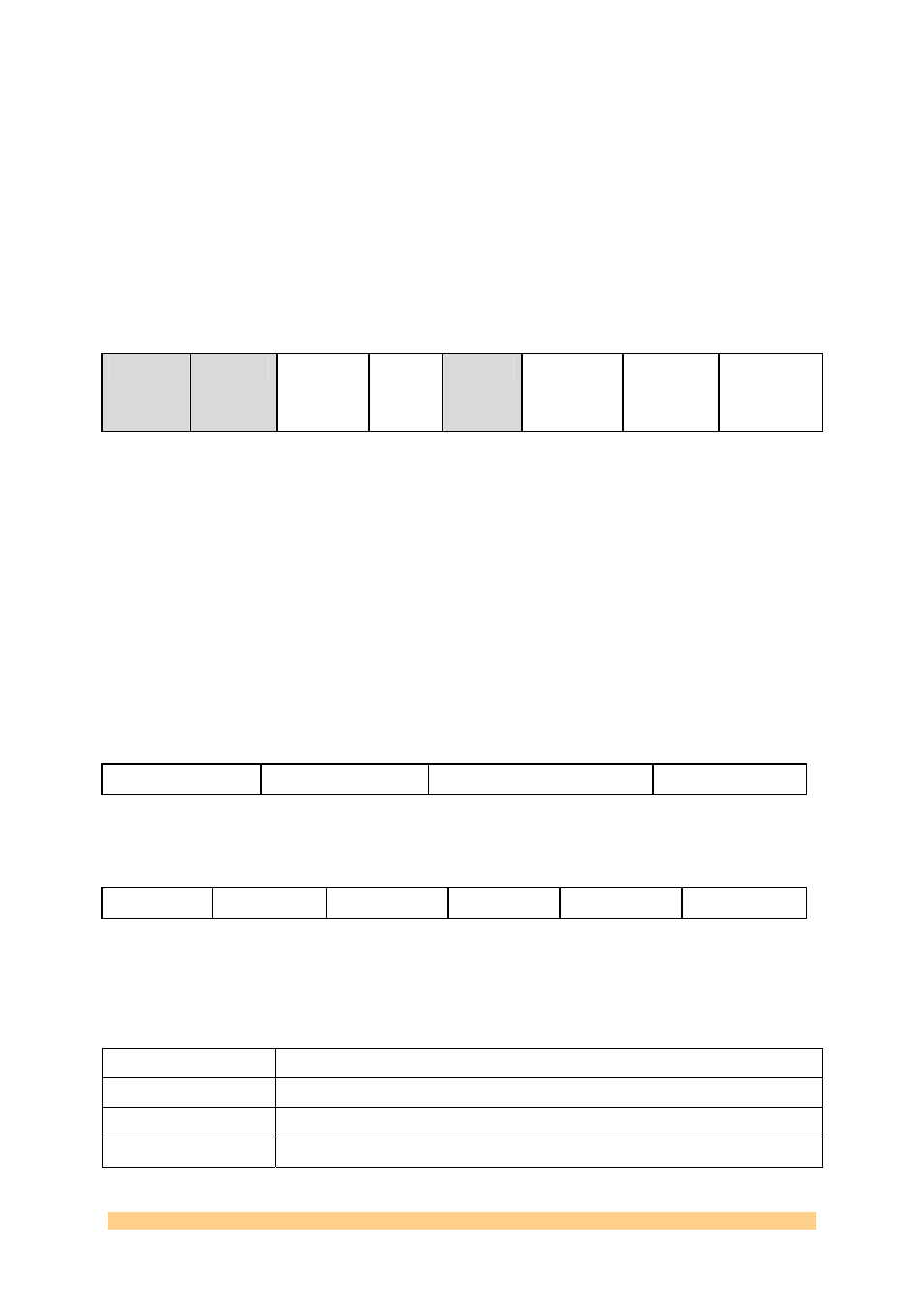
4.5.4.2 Control Register 3 = VME Interrupt Masks
A VME interrupt can be generated by any of the following sources:
TIM sites 1 and 4 signal IIOF0
Comm port interface
Software
The interrupt level is selected by bits 12-10 of Control Register 4. This VME interrupt is
masked or enabled by control register 3 bits.
31-16 15-11 10
9 8-3 2
1
0
TIM4
IIOF0
TIM1
IIOF0
Comm
port
-Txfull
Comm
port
-Rxemp
Soft int
R, 0000
0000
R, 0000
0
RW, 0
RW, 0
R,
000000
RW, 0
RW, 0
RW, 0
4.5.4.3 Control Register 4 = VME bus master cycle control
Some of the signals generated by the VME bus master are statically defined in this 32 bit
register. It also controls which comm port interface is enabled.
31-24 23-18 17
16
VME A31-24
VME AM5-0
VME A0/LWORD
VME A1
R, 0000 0000
R, 000000
R, 0
R, 0
15 14-13
12-10
9 8 7-0
VXC1/2
VME BRxx
VME IntLev
DS1
DS0
VME Iack
R, 0
R, 00
R, 000
R, 0
R, 0
R, 0000000
Bit Mnemonic
Description
VME A32-24
VME bus master address bits 32-24
VME AM5-0
VME bus master address modifier bits 5-0
VME A0/LWORD
VME bus master address bit A0/lword
User Manual SMT329
Page 37 of 52 Last
Edited:
09/02/2007
10:58:00