Super Systems 7EK 31080 User Manual
Page 7
3
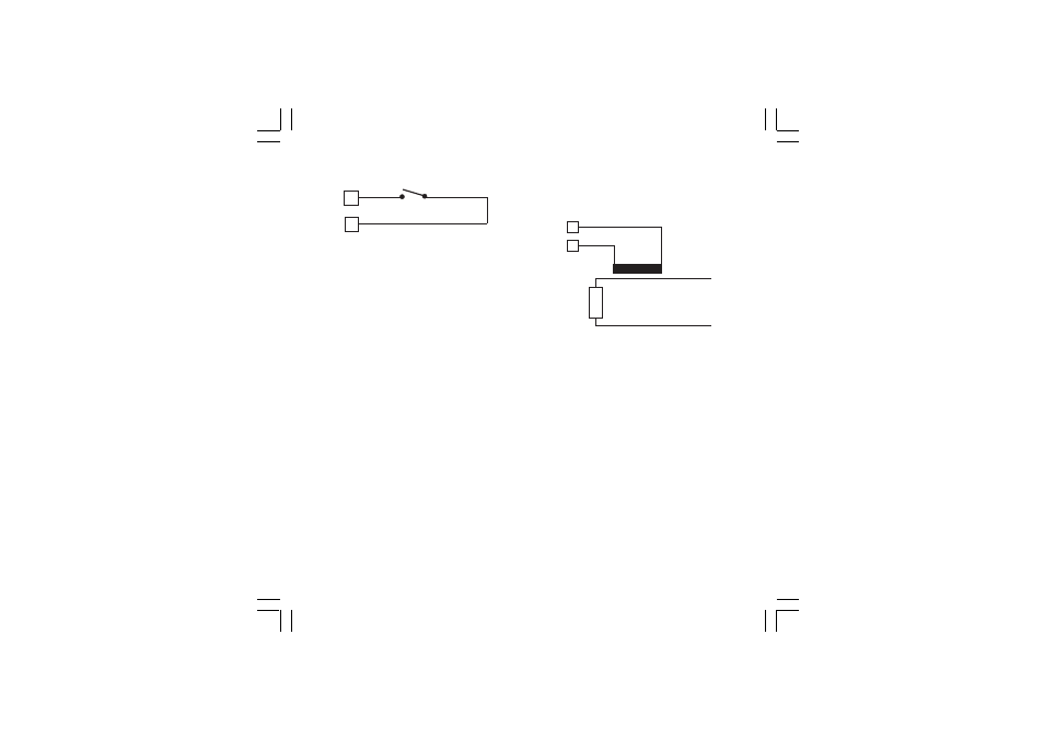
B) LOGIC INPUT
Fig. 5 - LOGIC INPUT WIRING
This logic input allows to select the operative set point.
logic input
op. set point
open
SP
close
SP2
Safety notes:
1) Do not run logic input wiring together with power
cables.
2) Use an external dry contact capable of switching 0.5
mA, 5 V DC.
3) The instrument needs 100 ms to recognize a contact
status variation.
4) The logic input is NOT isolated by the measuring input
8
SP / SP2
7
CURRENT TRANSFORMER INPUT
This input allows to measure and display the current
running through the load, driven by the OUTPUT 1, during
the ON and the OFF period of the OUT 1 cycle time.
By this features it is also available the "Out 1 failure
detection" function (see page 18)
Fig. 6
CURRENT TRANSFORMER INPUT
WIRING
NOTES:
1) The input impedance is equal to 10
W
.
2) The maximum input current is equal to 50 mA (50 / 60
Hz).
3) The minimum period (ON or OFF) to perform this
measurement is equal to 400 ms.
Scaling: programmable from 10 A to 100 A (with 1A
step).
Resolution:
- for full scale up to 20 A: 0.1 A.
- for full scale from 21 A to 100 A: 1 A
Safety note:
-
Do not run current transformer input wiring together
with power cables.
Load
Current
transformer
6
5
31080-1-00.p65
3/24/00, 11:58 AM
3