Super Systems 7EK 31080 User Manual
Page 8
4
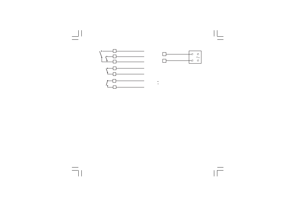
VOLTAGE OUTPUT FOR SSR DRIVE
Fig. 8 SSR DRIVE OUTPUT WIRING
It is a time proportioning output.
Logic level 0: Vout < 0.5 V DC.
Logic level 1:
- 14 V + 20 % @ 20 mA
- 24 V + 20 % @ 1 mA.
Maximum current = 20 mA.
NOTES:
1) This output is not isolated. A double or reinforced
isolation between instrument output and power supply
must be assured by the external solid state relay.
2) Relay output and SSR drive output are both available.
For the SSR output selection see "Preliminary
hardware settings" chapter.
C) RELAY OUTPUTS
Fig. 7 RELAY OUTPUTS WIRING
The outputs 1 and 2 are protected by varistor against
inductive load with inductive component up to 0.5 A.
The contact rating of the OUT 1 is 3A/250V AC resistive
load.
The contact rating of the OUT 2, 3 and 4 is 2A/250V AC
resistive load.
The number of operations is 1 x 10
5
at specified rating.
NOTES:
1) To avoid electrical shock, connect power line at the
end of the wiring procedure.
2) For power connections use No 16 AWG or larger wires
rated for at last 75 °C.
3) Use copper conductors only.
4) Don’t run input wires together with power cables.
5) Relay output and SSR drive output are both available.
For the relay output selection see "Preliminary
hardware settings" chapter.
18
16
17
NO - OUT 4
NO - OUT 3
C - OUT 3 e 4
OUT 3
OUT 4
19
20
C - OUT 2
NO - OUT 2
OUT 2
21
22
NO - OUT 1
C - OUT 1
OUT 1
SOLID STATE
RELAY
+
_
_
+
14
15
OUT 1
31080-1-00.p65
3/24/00, 11:58 AM
4