Super Systems 7EK 31081 User Manual
Page 6
1
MOUNTING REQUIREMENTS
This instrument is intended for permanent installation, for
indoor use only, in an electrical panel which encloses the
rear housing, exposed terminals and wiring on the back.
Select a mounting location where there is minimum
vibration and the ambient temperature range between 0
and 50 °C.
The instrument can be mounted on a panel up to 15 mm
thick.
For outline and cutout dimensions refer to page IV.
The surface texture of the panel must be better than
6,3
m
m.
The instrument is shipped with rubber panel gasket.
To assure the IP65 and NEMA 4 protection, insert the
panel gasket between the instrument and the panel as
shown in fig. 1.
While holding the instrument against the panel proceed as
follows:
1) insert the gasket in the instrument case;
2) insert the instrument in the panel cutout;
3) pushing the instrument against the panel, insert the
mounting bracket;
4) with a screwdriver, turn the screws with a torque
between 0.3 and 0.4 Nm.
CONNECTIONS
A) MEASURING INPUTS
NOTE: Any external components (like zener barriers ecc.)
connected between sensor and input terminals may cause
errors in measurement due to excessive and/or not
balanced line resistance or possible leakage currents.
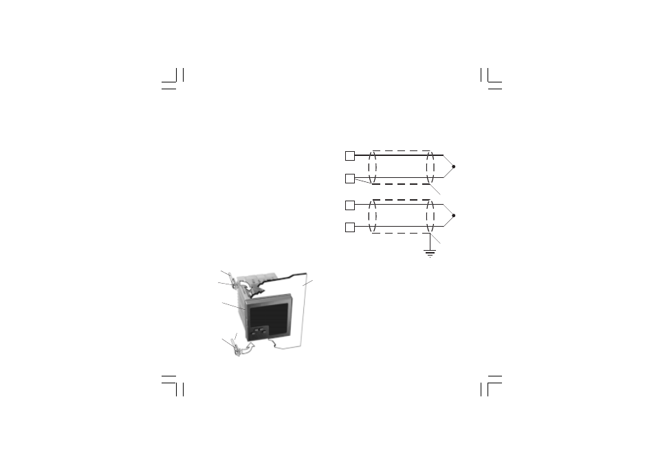
TC INPUT
Fig. 2 THERMOCOUPLE INPUT WIRING
External resistance: 100
W
max, maximum error 0,1% of
span.
Cold junction: automatic compensation from 0 to 50 °C.
Cold junction accuracy : 0.1 °C/°C
Input impedance: > 1 M
W
Calibration : according to IEC 584-1 and DIN 43710 -
1977.
NOTE:
1)
Don’t run input wires together with power cables.
2)
For TC wiring use proper compensating cable
preferable shielded.
3)
when a shielded cable is used, it should be connected
at one point only.
1
3
+
_
1
3
+
_
Shield
Shield
panel
screw
Fig. 1
bracket
gasket
screw
bracket
31081-1-00.p65
3/24/00, 11:59 AM
1