Cold junction offset, Satellite boxes – Super Systems DAQ User Manual
Page 26
Super Systems Inc. Page 26 of 34
DAQ Operations Manual
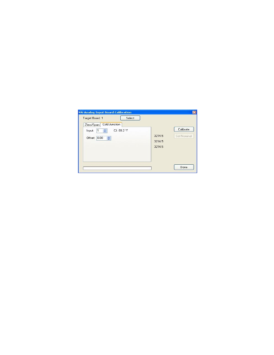
Cold Junction Offset
The second step in the calibration process is setting the cold junction offset. If necessary,
select a board to calibrate by clicking on the Select button. This will display a drop-down list
that the user can select the board to calibrate. This list will only display the available boards to
calibrate. Select the board’s input to apply the cold junction offset to by using the up and down
arrows. Select the appropriate offset to use by using the up and down arrows. This can range
from -25.00 to 25.00.
Note – To subtract a value from the current cold junction value, be sure to
set the offset value as a minus value by clicking on the plus/minus key on the keypad (+/-)
.
The
overall Cold Junction value is modified by adding or subtracting a value to the current value.
Press the Calibrate button to begin the calibration process.
Press the Done button to close out the screen.
Satellite Boxes
The satellite boxes represent expandable input slots for the Video Recorders which can be
mounted remotely and connected back to the main Video Recorder unit using the RS485 ports.
These satellite boxes will give customers the ability to add inputs to the Video Recorder.
The SR3 (pictured) contains three additional inputs for the Video Recorder. The satellite box SR6
contains six additional inputs, while the other satellite boxes contain the number of inputs
denoted by the number after the “SR”: SR9, SR12, SR15, SR18, and SR21.
To connect the satellite box back to the main Video Recorder unit, the “Remote RS485” on the
satellite box must be wired into the “RS485 Remote” on the main unit. 24VDC need to be
provided to the satellite box either by using a jumper from the main VR unit or from a separate
source.