Port 3 and port 4 pinout – Verilink 9000 Series (34-00271) Product Manual User Manual
Page 52
30
C
HAPTER
2: I
NSTALLATION
Port 3
and
Port 4
Port 3 and Port 4 of the 9111 are DCE ports with an RS-232 interface. Table 2-14
shows the pinout of Port 3 and Port 4.
9111 Dual
RS-232
Expansion
Option
Module
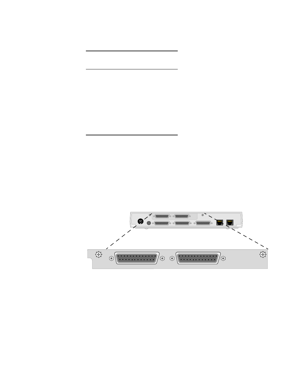
This section describes the 9111 Dual RS-232 Expansion Option Module. The
module is a two-port RS-232C serial interface card for the 9111 MultiPro series
unit. The module has two female DB-25 connectors (Port 5 and Port 6) and
occupies the same expansion slot as the Ethernet option card shown in Figure 2-4.
The interfaces for the module expand the capabilities of the 9111 to five ports. The
two expansion ports can be configured for either DCE or DTE by positioning the
jumpers located on the circuit board (see Figure 2-11). All other parameters are
configured through the console interface or through the NMCS program the same
as the other serial ports.
Table 2-14
Port 3 and Port 4 Pinout
x
Pin
Signal
RS-232C
Circuit
Symbol
1
Shield Ground
AA
2
Transmit Data
Ba
3
Receive Data
BB
4
Request to Send
CA
5
Clear to Send
CB
6
Data Set Ready
CC
7
Signal Ground
AB
8
Data Carrier Detect
CF
15
Transmit Clock
DB
17
Receive Clock
DD
PWR
RESET
SUPERVISORY
PORT 1
PORT 2
PORT 3
PORT 4
PORT 6
PORT 5
1
13
14
25
1
13
25
Figure 2-10 Front View of the 9111 Dual RS-232 Expansion Module
PORT 6
PORT 5
1
13
14
25
1
13
14
25