Description, Mounting, Vav system – WattMaster MG331-21-VAVCAV User Manual
Page 25: Input available, Output available, Page, 1 of 1
Form: WMS-OE331-21-KWH-Module-01A.doc
Page
1 of 1
VAV System
Description
The OE331-21-KWH (Kilowatt Hour)
Module provides the ability to record and
display KW usage and to limit demand.
Using the Prism Graphical Computer
Front End, a status screen displays cur-
rent demand, yesterday’s demand, and
the peak demand values and times for
both. Historical logs from the previous
month and the current month are also
available and can be downloaded for
archiving via the PRISM software inter-
face. A running total of power consump-
tion is also displayed on the Status
Screen. This value can be manually re-
set at any time allowing the user to moni-
tor overall power consumption over long
periods of time.
Analog Input #2 on the KWH Module
monitors all incoming contact closures
from a KW pulse meter (usually provided
by the utility company) and times them to
generate the current KW Demand. A
user adjustable setpoint is provided to
define what each pulse represents in
Kilowatts Per Hour. A Demand Factoring
Constant is also provided if it appears that contact bounce may be affecting the operation. The Demand Factor is
simply the number of times to average the current demand reading to create the final Demand Reading. It is nor-
mally left at a value of '1' unless a problem is encountered.
Two additional setpoints are provided for the EMS Demand Limiting Broadcast. A Limit Setpoint and a Propor-
tional Reset Range are provided so that the user can adjust when to begin shedding demand and how rapidly
this occurs. Any controllers equipped to "hear" this broadcast begin spreading their heating and cooling setpoints
proportionally until the maximum EMS Adjustment limit is reached. This value is also user adjustable for each
individual controller so that the rate at which demand is shed can be optimally configured for special cases where
not all zones can tolerate a large change in temperature.
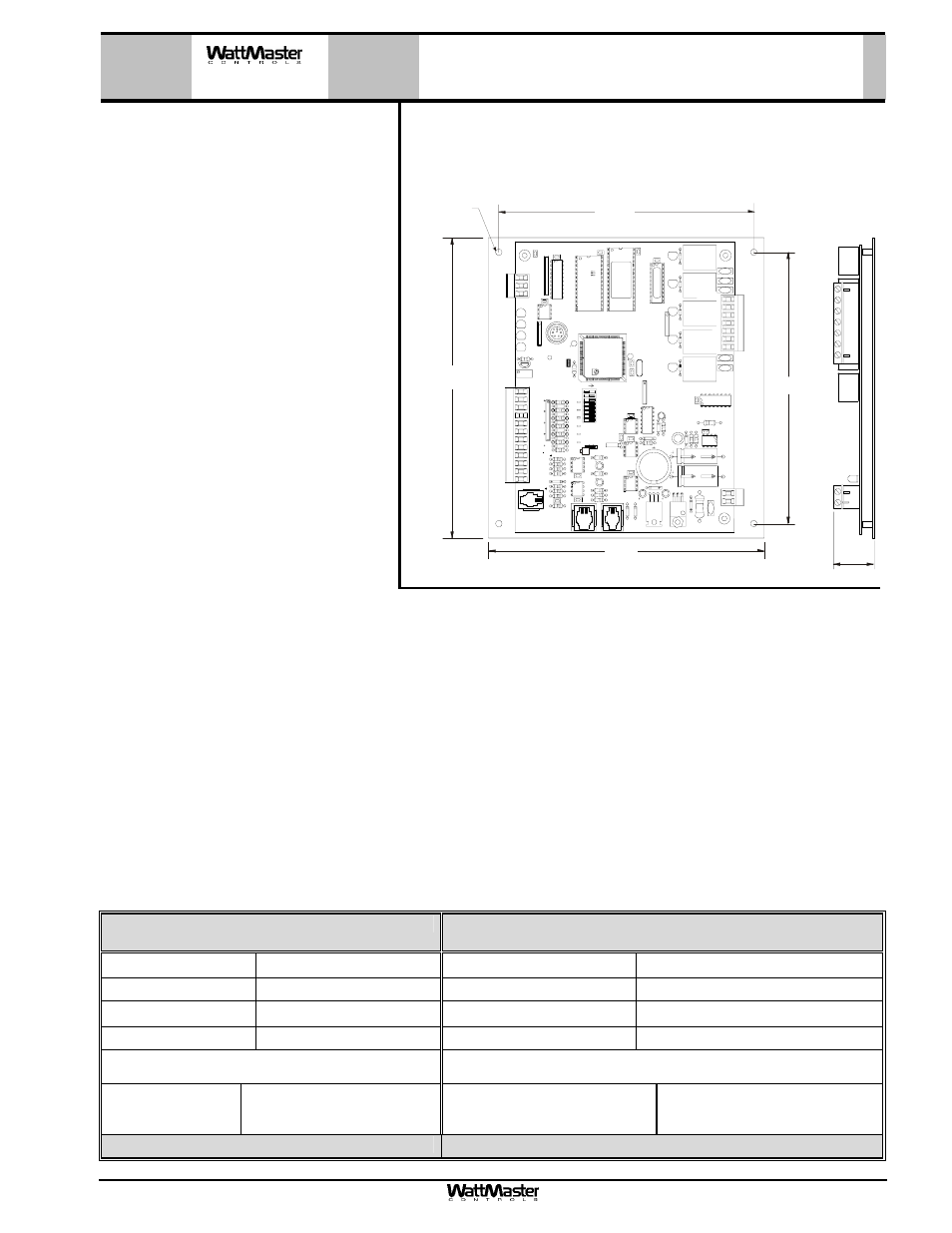
Mounting
The KWH Module is provided with an integral backplate for mounting inside of a control enclosure. It is recom-
mended that the KWH Module be mounted in the HVAC unit control enclosure, or in a control enclosure in the
building equipment room. An optional factory control enclosure for the KWH Module is available.
OE331-21-KWH
KWH Module
Technical Data
OE331-21-KWH
KWH Module
Power
24 Volt AC
Weight
1.5 lb.
Power Consumption
8 VA Maximum
Network Connection
RS-485
Operating Temp
10
°F to 149°F Protocol
HSI Open Protocol Token Passing
Operating Humidity
90% RH Non-Condensing
Communications
RS-485 - 9600 Baud
Input Available
Output Available
AIN2
Dry Contact Closure from
KW Pulse Meter (By Others)
RS-485 Communications Loop
EMS Demand Limiting
Broadcast
Three Year Warranty
WattMaster reserves the right to change specifications without notice
RL
Y
1
D1
D2
D3
D4
D5
CX
3
RAM
EPROM
C3
C2
U6
PH
IL
IP
S
CX6
C1
CX2
U2
U3
PAL
CX4
U4
TUC-5R PLUS
YS101816 REV. 2
V1
V2
V3
V5
V4
TB2
4
NETWORK
TOKEN
16
32
8
SW1
ADD
2
1
ADDRESS
V6
PO
W
E
R
GND
24VAC
L1
D1
6
R6
C9
SC1
R1
1
U1
1
MC
34064
A
D1
3
C16
9936
VR2
7824C
T
M
TB4
R27
C13
R1
0
VR1
C1
9
C1
8
NE5090NPB3192
0PS
U8
CX
8
U9
X1
R7
D1
0
R13
D12
C7
CX10
U10
CX12
U12
U14
CX14
PJ3
PJ2
PJ1
EXPANSION
PRESSURE
SENSOR
T'STAT
C17
D15
R26
C20
R25
R24
R22
U15
CX13
U13
C15
R19
R15
C14
D1
8
D1
7
PU1
PU2
PU3
PU4
PU5
PU7
D6
D7
D8
D9
D11
D14
C12
C10
0-
5
VD
C
0-
1
VD
C
JP1
C1
1
X2
GND
TB3
INPUTS
GND
GND
+VDC
AIN1
AIN2
AIN3
AIN4
AIN5
AOUT1
AOUT2
AIN7
RN
4
1
RN5
RS-485
CX5
U5
R
TB1
SHLD
T
COMM
COMM
RN
3
1
RN1
U1
CX1
1
LD6
COMM
PWR
LD7
LED1
LED2
LD9
LD8
R1
U7
RV1
VREF ADJ
R28
+VREF
5.11V
TEST POINT
EWDOG
D19
RN2
1
COM1-3
COM4-5
R5
R4
R3
R2
R1
RL
Y
2
RL
Y
3
RL
Y
4
RL
Y
5
CX15
(1 MEG)
HH
P1
C2
1
6.2“
6.6”
7.3”
6.7”
1.1”
.20 Dia.
Typ. of 4