Oe510-xx-vav – pressure dependent, Round damper, Round damper sizing – WattMaster MG331-21-VAVCAV User Manual
Page 27: Round damper selection data
Form: WM-OE510-RndDmpr-Sub-01A
Page
2 of 2
VAV System
Round Damper Sizing
Use a load program to determine the peak
load for each zone. These calculations will be
used to select Round Damper sizes.
The WMVAV System utilizes a typical low
pressure duct design. To reduce noise prob-
lems, duct pressures should not exceed 1”
W.C.
Primary trunk ducts used with WMVAV sys-
tems should not be “undersized”. This is es-
pecially true of “pressure dependent” sys-
tems. With larger trunk ducts, it is easier to
assure relatively constant pressure to each
Round Damper. Runs should be as short as
possible, and the trunk duct system kept as
symmetrical as possible to facilitate system
balancing. Wherever possible, run the trunk
ducts above corridors and locate the Round
Dampers above corridors to reduce the noise
in the space and facilitate service of the
valves. Trunk ducts should be sized for no
more than 0.1” W.C. drop per 100 ft. of duct,
and a maximum duct velocity of 2000 FPM.
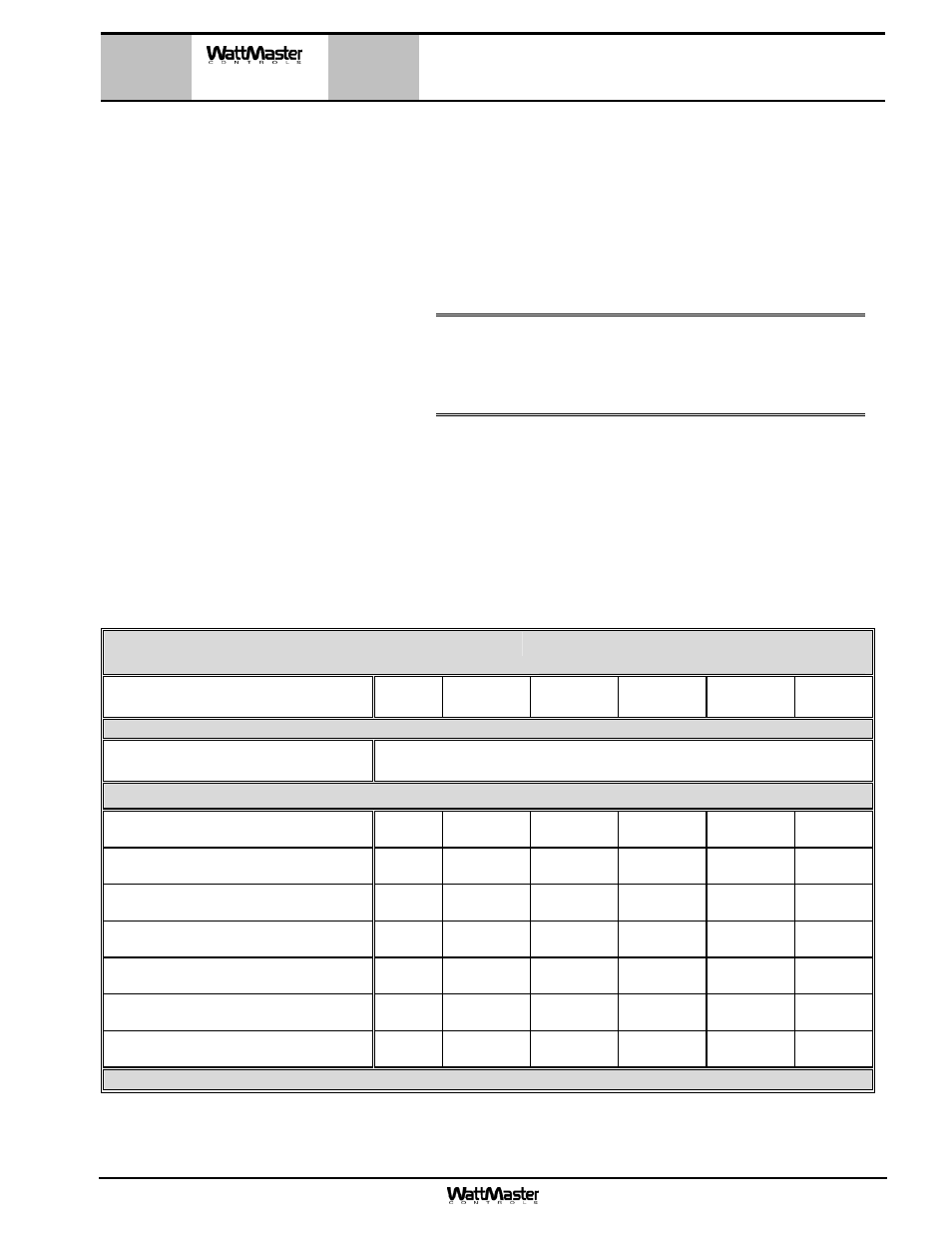
Round Damper Selection Data
OE510-XX-VAV Pressure Dependent
Round Damper
Round Damper Round Duct Size
(Area Ft
2
)
6”
(0.188)
8”
(0.338)
10”
(0.532)
12”
(0.769)
14”
(1.050)
16”
(1.375)
Velocity Through Round Damper
FPM
Airflow Through Round Damper - CFM
(
ΔP
S
inches W.C. w/ Damper Full Open)
500
94
(0.01)
169
(0.01)
266
(0.01)
385
(0.01)
525
(0.01)
687
(0.01)
750
141
(0.03)
254
(0.02)
399
(0.01)
577
(0.02)
788
(0.01)
1031
(0.01)
1000
188
(0.05)
338
(0.03)
532
(0.02)
769
(0.03)
1050
(0.02)
1375
(0.01)
1250
235
(0.07)
423
(0.04)
665
(0.03)
961
(0.04)
1313
(0.03)
1718
(0.02)
1500
282
(0.09)
507
(0.06)
798
(0.04)
1154
(0.05)
1575
0.04)
2062
(0.03)
1750
329
(0.12)
592
(0.08)
931
(0.06)
1346
(0.06)
1838
(0.05)
2405
(0.04)
2000
376
(0.15)
676
(0.10)
1064
(0.07)
1538
(0.07)
2100
(0.07)
2749
(0.05)
WattMaster reserves the right to change specifications without notice
Using the maximum acceptable velocity for a branch duct (typi-
cally 1000-1500 FPM for minimal noise), find the smallest
Round Damper that will deliver the required CFM as determined
by the load program. Locate the branch velocity used in the
duct design program in the left hand column of the Round
Damper Selection Data table. Move across the table and find
the Round Damper, which will provide the acceptable CFM to
meet the zone airflow requirements.
Note:
Compare the Round Damper size selected against
the duct size to determine if the next size up or
down will provide acceptable performance without
requiring a transition fitting.
OE510-XX-VAV – Pressure
Dependent
Round Damper