Wall mounted humidity sensor – WattMaster MG331-21-VAVCAV User Manual
Page 42
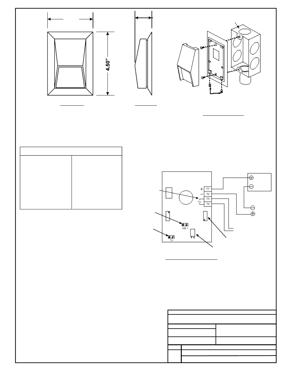
3.23”
1.25"
Notes:
FILENAME
DATE:
B. CREWS
DESCRIPTION:
PAGE
DRAWN BY:
Wall Mounted Humidity Sensor
1
JOB NAME
2.)All Wiring To Be In Accordance With
Local And National Electrical Codes
And Specifications.
3.)These Wiring Instructions Are
Typical For All Sensor Applications.
See Controller Wiring Diagrams For
Detailed Wiring Instructions and
Terminations For Your Specific
Application.
012/18/02
G-HUMSRWALL1.CDR
OE265-01
Front View
Side View
Mounting Diagram
See Note 1
Typical Wiring Diagram
Humidity Sensor Current/Voltage Chart
RH
Output*
Output
mA
VDC*
0 ...............4.00 ...........1.00
5 ...............4.80 ...........1.20
10 ..............5.60 ...........1.40
15 ..............6.40 ...........1.60
20 ..............7.20 ...........1.80
25 ..............8.00 ...........2.00
30 ..............8.80 ...........2.20
35 ..............9.60 ...........2.40
40 ..............10.40 .........2.60
45 ..............11.20 .........2.80
50 ..............12.00 .........3.00
%
RH
Output*
Output
%
mA
VDC*
55 ..............12.80 .........3.20
60 ..............13.60 .........3.40
65 ..............14.40 .........3.60
70 ..............15.20 .........3.80
75 ..............16.00 .........4.00
80 ..............16.80 .........4.20
85 ..............17.60 .........4.40
90 ..............18.40 .........4.60
95 ..............19.20 .........4.80
100............ 20.00.........5.00
1.)The sensor is designed to be wall
mounted in rooms where appearance
is important. It may be mounted
directly on dry wall or on any single
gang electrical outlet box with no
adapters required. Toggle bolts or
other direct wall mount screws can be
used where conduit is not required. It
includes a detachable mounting plate.
The cover is secured with tamper-
resistant hex screws. The sensor
should be mounted approximately five
feet above the floor, on an interior wall,
away from any heating or cooling
generating devices. Plug the wireway
hole to prevent false readings by air
drafts within the wall.
See Note 3
Wall Mount Relative Humidity Sensor OE265-01
*Chart Notes:
1. Be sure that +24VDC power is being supplied to the sensor. For
voltage measurement s
onnect the
meter between ground and the input terminal on the controller
board that is connected to the sensor. The input on the controller
board must have a 250 ohm resistor to ground installed and have
it’s associated pull-up resistor removed for the sensor to function
properly. For current measurement set the ammeter to DC Amps
and connect the meter’s lead in series with the T1 terminal on the
sensor. Use an accurate humidity measurement device to
determine RH (relative humidity) such as an aspirating
psychrometer. Use the Output VDC column to read the Output
Voltage or the Output mA column to read the Output Amperage
corresponding with the RH percentage measured with the
psychrometer. If the measured voltage or amperage is within 3%
of what is listed for the corresponding RH, then the sensor is
functioning properly.
et the meter to DC Volts. C
Cover Mounting
1/16” Allen Screws
Optional Customer
Supplied Handibox
Power
Supply
24 VDC
4-20 Ma
Signal
To Temperature Input
(When Used)
Calibration Pot Zero
Humidity Sensing Element
Terminals For
Thermistor And/Or
Membrane Switch
Option (N.O. Only)
Switch Pins For
Membrane Switch
Option
Optional
Thermistor
Soldering
Connector
Pins