Return air humidity sensor – WattMaster MG331-21-VAVCAV User Manual
Page 41
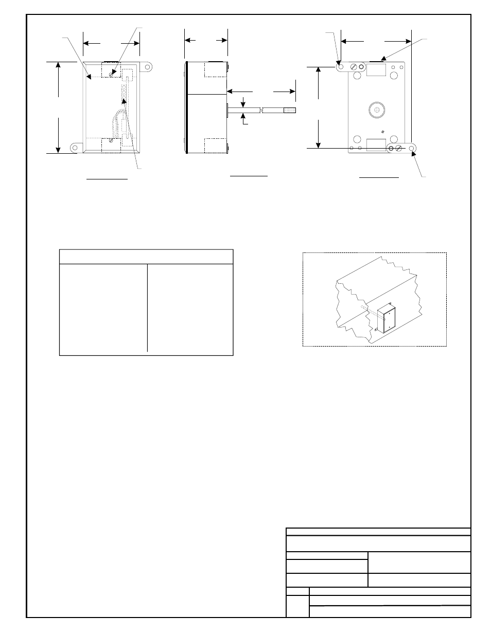
8.00“
0.38“
Notes:
FILENAME
DATE:
B. CREWS
DESCRIPTION:
PAGE
DRAWN BY:
Return Air Humidity Sensor
1
JOB NAME
4.)All Wiring To Be In Accordance With
Local And National Electrical Codes
And Specifications.
3.)TheSensor Probe Gasket Must Be
Installed Between the Back of the
Sensor Box and the Duct to Provide an
Airtight Seal.
04/25/02
G-HUMSRIR1.CDR
OE265-04
Front View
Side View
Back View
Humidity Sensor Current/Voltage Chart
RH
Output*
Output
mA
VDC*
0...............4.00...........1.00
5...............4.80...........1.20
10..............5.60...........1.40
15..............6.40...........1.60
20..............7.20...........1.80
25..............8.00...........2.00
30..............8.80...........2.20
35..............9.60...........2.40
40..............10.40.........2.60
45..............11.20 .........2.80
50..............12.00.........3.00
%
RH
Output*
Output
%
mA
VDC*
55..............12.80.........3.20
60..............13.60.........3.40
65..............14.40.........3.60
70..............15.20.........3.80
75..............16.00.........4.00
80..............16.80.........4.20
85..............17.60.........4.40
90..............18.40.........4.60
95..............19.20.........4.80
100............20.00.........5.00
4.63“
2.25“
Closure Plug
CAUTION!
See Note 2
Gasketed Cover
CAUTION!
See Note3
2.)Unused Conduit Opening(s) Must
Have Closure Plugs Installed to
Prevent Dust or Insects Infiltrating the
Sensor Electrical Box..
1.)The Sensor Should Be Mounted so
that the 8“ Probe is in the Center of
the Return Air Duct. It Should be
Mounted Away from Fans, Elbows,
Heating or Cooling Coils or Other
Equipment that Could Affect the
Measurement of Relative Humidity.
Also, the Sensor Should be
Mounted in an Area that Receives
Adequate Air Flow for Accurate
Operation. The Sensor may be
Mounted Horizontally or Vertically to
the Return Air Duct..
0.19 Dia.
Hole Typ.
Cover
Mounting
Screw
Wiring Terminal.
Connect Wiring
To Controller Using
24 Gauge Minimum
Wire. Only 2 Conductors
are Required.
-
Typ.
Return Air Relative Humidity Sensor OE265-04
Mounting Tab
& Screw - Typ.
*Chart Notes:
1. Be sure that +24VDC power is being supplied to the sensor. For voltage measurement s
onnect the meter between ground and the input terminal on the controller
board that is connected to the sensor. The input on the controller board must have a 250 ohm
resistor to ground installed and have it’s associated pull-up resistor removed for the sensor to
function properly. For current measurement set the ammeter to DC Amps and connect the
meter’s lead in series with the T1 terminal on the sensor. Use an accurate humidity
measurement device to determine RH (relative humidity) such as an aspirating psychrometer.
Use the Output VDC column to read the Output Voltage or the Output mA column to read the
Output Amperage corresponding with the RH percentage measured with the psychrometer. If the
measured voltage or amperage is within 3% of what is listed for the corresponding RH, then the
sensor is functioning properly.
et the
meter to DC Volts. C
1/2
See Note #1
Mounting Sensor to Duct
2.88“
3.50“
3.19“