AEC Econo-Cool Chillers User Manual
Page 52
AEC Water Temperature Control Units
Page 51
Figure 8
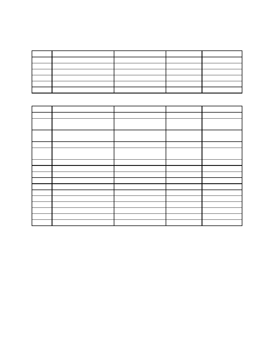
Setting List for Process Temperature Controller
Mode
Parameter
Setting range
Default
Solenoid Valve
Protect SECr Security
0 to 6
1
5
Protect KEYP A/M Key protect
ON/OFF
OFF
ON
Level 0 PV/SV display
—
—
—
Level 0 Switch to Manual mode
-5.0 to 105.0%
0.0
Default
Level 0 MV monitor
Cannot be set
0.0
Default
Level 0 r-S Run/Stop
Run/Stop
Run
Default
Mode
Parameter
Setting range
Default
Solenoid Valve
Level 1 At AT Execute/Cancel
OFF/AT-1/AT-2
0
Default
Level 1 SP-0 Set point 0
Set point lower limit to
Set point upper limit
0 Default
Level 1 SP-1 Set point 1
Set point lower limit to
Set point upper limit
0 Default
Level 1 AL-1 Alarm value 1
-1999 to 9999 EU
0
Default
Level 1 AL-2 Alarm value 2
-1999 to 9999 EU
0
0=full heat,
+10=half heat
Level 1 AL-3 Alarm value 3
-1999 to 9999 EU
0
Default
Level 1 P Proportional band
0.1 to 999.9% FS
10.0
0.5
Level 1 I Integral time
0 to 3999 SEC
233
55
Level 1 d Derivative timer
0 to 3999 SEC
40
9
Level 1 C-SC Cooling coefficient
0.01 to 99.99
1.00
Default
Level 1 C-db Dead band
-19.99 to 99.99
0.00
Default
Level 1 oF-r Manual reset valve
0.0 to 100.0
50.0
Default
Level 1 HYS Hysteresis (heat)
0.01 to 99.99
0.10
Default
Level 1 CHYS Hysteresis (cool)
0.01 to 99.99
0.10
Default
Level 1 CP Control period (heat)
1 to 99 SEC
20
15
Level 1 C-CP Control period (cool)
1 to 99 SEC
20
Default