Servicing the fluid pump – AIRLESSCO SS4550 User Manual
Page 18
16
17
2
1
9
3
4
5
6
7
10
11
4
12
13
8
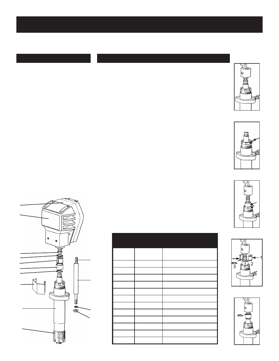
SERVICING THE FLUID PUMP
FLUID PUMP DISCONNECT
FLUID PUMP REINSTALL
1. Flush out the material you are
spraying, if possible.
2. Follow the Pressure Relief
Procedure on page 8. Stop the
pump in the middle of down
stroke.
3. Remove the suction tube and fluid
hose (if so equipped) from the
fluid pump.
4. Remove the connecting rod shield
from the pump.
5. Remove 2 retaining rings and slip
the sleeve of the coupling down
and remove both coupling halves.
This will disconnect fluid pump
from the connecting rod.
6. Using a 7/8” box wrench,
disconnect the high pressure fluid
line from the pump.
7. Using a 9/16” wrench, unscrew
the two tie rod locknuts.
8. Pull the pump off the tie rods.
1. Loosen the packing nut & extend piston rod to fully up position.
Slip sleeve over the piston rod. See figure 15.
2. Insert one of the retaining rings through the packing nut and
rest the sleeve on top of it. See figure 16 & 17.
3. Connect the connecting rod with the fluid pump by installing
the coupling halves. Slide sleeve over the coupling halves and
secure with retaining ring. See figure 18.
4. Remove the retaining ring from the packing nut and insert into
coupling halves. See figure 19
5. Secure the fluid pump housing to the tie rods and screw
locknuts with washers on loosely.
6. Tighten the tie rod locknuts evenly to 30 ft. lb.
NOTE: AFTER ALL THE ROD LOCKNUTS ARE TIGHT, THE
ALIGNMENT OF BOTH RODS SHOULD ALLOW EASY ASSEMBLY
AND DISASSEMBLY OF THE COUPLING. IF ANY BINDING, LOOSEN
AND RETIGHTEN ALL THE ROD LOCKNUTS TO IMPROVE THE
ALIGNMENT. MISALIGNMENT CAUSES PREMATURE WEAR OF
SEAL AND PACKINGS.
7. Tighten packing nut clockwise until resistance against the
packings can be felt. Turn it one full turn more.
8. Start the pump and operate it slowly (at low engine speed)
to check the piston rod for binding. Adjust tie rod lock nuts if
necessary to eliminate binding.
9. Prime the unit and run at maximum pressure for several
minutes, then release the pressure & repeat step 7.
10. Fill the wet cup (packing nut) with five drops of TSO (Throat
Seal Oil).
NOTE: CHECK EVERYTHING IN THE TROUBLESHOOTING CHART BEFORE DISASSEMBLING THE SPRAYER.
PARTS LIST FIGURE 13
Item No.
Part No.
Description
1
301-203-99
301-204-99
Gearbox 3/4” (810/910E)
Gearbox 1” (1100/1110E)
2
301-320
Cover
3
301-046
Rod End
4
189-048
Retaining Ring
5
189-046
Coupling Set
6
198-047
Retaining Sleeve
7
301-467
Front Shield
8
187-410
SL Paint Pump Assy
9
187-002
Suction Nut
10
140-051
Nut (2)
11
140-035
Lock Washer (2)
12
301-059
Spacer (2)
13
100-328
Stud (2)
FIG. 13
FIG. 14
FIG. 15
FIG. 16
FIG. 17
FIG. 18