Clutch replacement, Fig. 27 – AIRLESSCO SS4550 User Manual
Page 26
24
25
REFER TO FIGURES 27-30
1. With gearbox held in a vice vertically as previously
described, place first spacer, and bearing, onto gearbox
shaft. See Fig. 28
2. Insert snap rings (2), into recesses of cog pulley portion
of clutch. Place cog pulley portion of clutch with cog belt
attached onto shaft.
3. Place second spacer, into cog pulley portion of clutch.
This spacer will rest on the first bearing, installed.
4. Insert second bearing, on top of upper snap ring,
5. Lay removable spacer on top of last bearing. If the
clutch air gap is larger than .024", do not use removable
spacer. Put spacer over removable spacer, if used, and
top bearing.
6. Place coil portion of clutch down onto cog pulley portion
of clutch and center on gearbox shaft.
7. Screw differential screw, into coupling screw and nut
until 1/16" is showing. See Fig. 28
8. Push coupling nut assembly, into clutch assembly until it
comes to a positive stop. (Differential screw comes into
contact with the threaded gearbox shaft.)
9. With 13/16" wrench on coupling screw and 5/16" allen
wrench in differential screw, simultaneously with both
wrenches screw coupling nut assembly into gearbox
shaft by turning clockwise until a positive stop is
reached.
10. Hold coupling nut ass'y and tighten diffential screw
to 30 ft.-lbs. This will expand the coupling assembly,
thereby holding the clutch assembly to gearbox shaft.
Turn clutch observing clutch gap. The pulley should
turn freely with a gap of .012 to .024" between the two
clutch faces. If the gap is greater than .024, remove
the removable spacer. Reassemble and check gap for
proper clearance.
11.Place cog belt over cog pulley portion of clutch. Set
gearbox and clutch assembly on the support brackets
(Fig 30, items 25 & 26), screw in the two vertical bracket
screws (Fig 30, item 20) and start the four horizontal
screws throught the gearbox plate (Fig 27, item 5) and
into the back of the gearbox.
12. Slide cog belt over engine pulley
INSPECTING THE CLUTCH
1. Inspect clutch and belt, replace as neccessary.
INSTALLING THE CLUTCH
13. Slightly loosen the two horizontal screws (Fig 31, items
19-22) that connect the top and bottom supports (Fig 31,
items 24 & 25).
14. Evenly tighten set screws (Fig 27, item 6) until flush with
tip of block tensioner (Fig 27, item 7) . Check tension on
cog belt by pressing hard with thumb. Proper tensioning
should allow for approximately 1/8". If belt is too loose,
tighten set screws further.
15. Once belt tension is correct tighten down the four
horizontal screws that go through the gearbox plate (Fig
30, item 8) and into the back of the gearbox. Also tighten
the two horizontal screws (Fig 31, items 19-20) that
connect the top and bottom supports (Fig 31, items 24 &
25). Reconfirm that the belt deflection is still 1/8".
15. Reassembly connections, covers and fluid pump in
reverse order as described in steps 1-7 of the "Removing
Clutch" instructions.
BELT TENSIONING
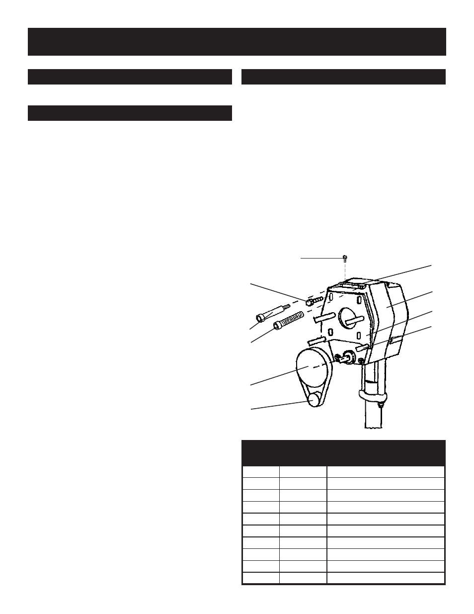
PARTS LIST FIGURE 27
Item No.
Part No.
Description
1
301-231
Cog Belt
2
301-284
Clutch Replacement
3
305-088
Screw
4
100-175
Shoulder Screw
5
100-173
Screw Flanged (4)
6
100-174
Set Screw (2)
7
301-534
Block Tensioner
8
301-208
Gearbox
9
305-045
Plate
10
305-046
Spacer Tube
CLUTCH REPLACEMENT
1
7
6
5
4
3
2
10
9
8
FIG. 27