Replacement of electrical control board, Fig. 26 – AIRLESSCO SS4550 User Manual
Page 24
22
23
REPLACEMENT OF ELECTRICAL CONTROL BOARD
1. Remove electrical cover.
2. Disconnect sensor lead from Electrical Board.
3. Disconnect two clutch leads on Electrical Board from
leads on clutch.
4. Using a 1/16" allen, loosen set screw in Pressure Control
Knob and remove knob.
1. Turn "Pressure Calibration" Trimpot adjustment on
electrical control board in the counter clockwise direction
at least 15 revolutions.
2. Connect 5000 psi glycerine pressure guage on outlet of
pump between fluid pump & airless hose to monitor Fluid
Pump Pressure.
3. Start engine and run at maximum RPM. Turn Prime
Valve to the open (Prime) position. Turn Pressure
Control Knob to maximum position (fully clockwise).
5. Using a 1/2" nutdriver or 1/2" deep socket, remove nut
from pressure control shaft. This will allow removal of
electrical control board from frame.
6. Replace Electrical Board Assembly in reverse order.
Adjust pressure as per procedure below, "Pressure
Calibration on the Electrical Control Board".
4. Using an insulated screwdriver, adjust "Pressure
Calibration" Trimpot by turning clockwise until the
clutch engages. When the clutch engages the pump
will commence Priming. When pump is primed, turn
the Prime Valve to the Closed (Pressure) Position.
THE PUMP WILL BEGIN TO PRESSURIZE AND THE
CLUTCH WILL DISENGAGE AT A LOW PRESSURE.
CONTINUE TURNING THE TRIMPOT CLOCKWISE
TO INCREASE PRESSURE TO 3000 PSI.
5. Trigger gun. The pressure should drop approximately
350-400 psi, the clutch will engage and build
pressure to 3000 psi and disengage. Trigger gun
several times to ensure proper pressure setting.
6. Turn Pressure Control Knob to minimum position.
The clutch should disengage and pump stop moving.
7. Secure leads with tie strap.
8. Replace cover on unit. Ensure the leads are not
pinched or damaged in the process of replacing
covers.
PRESSURE CALIBRATION OF THE ELECTRICAL CONTROL BOARD
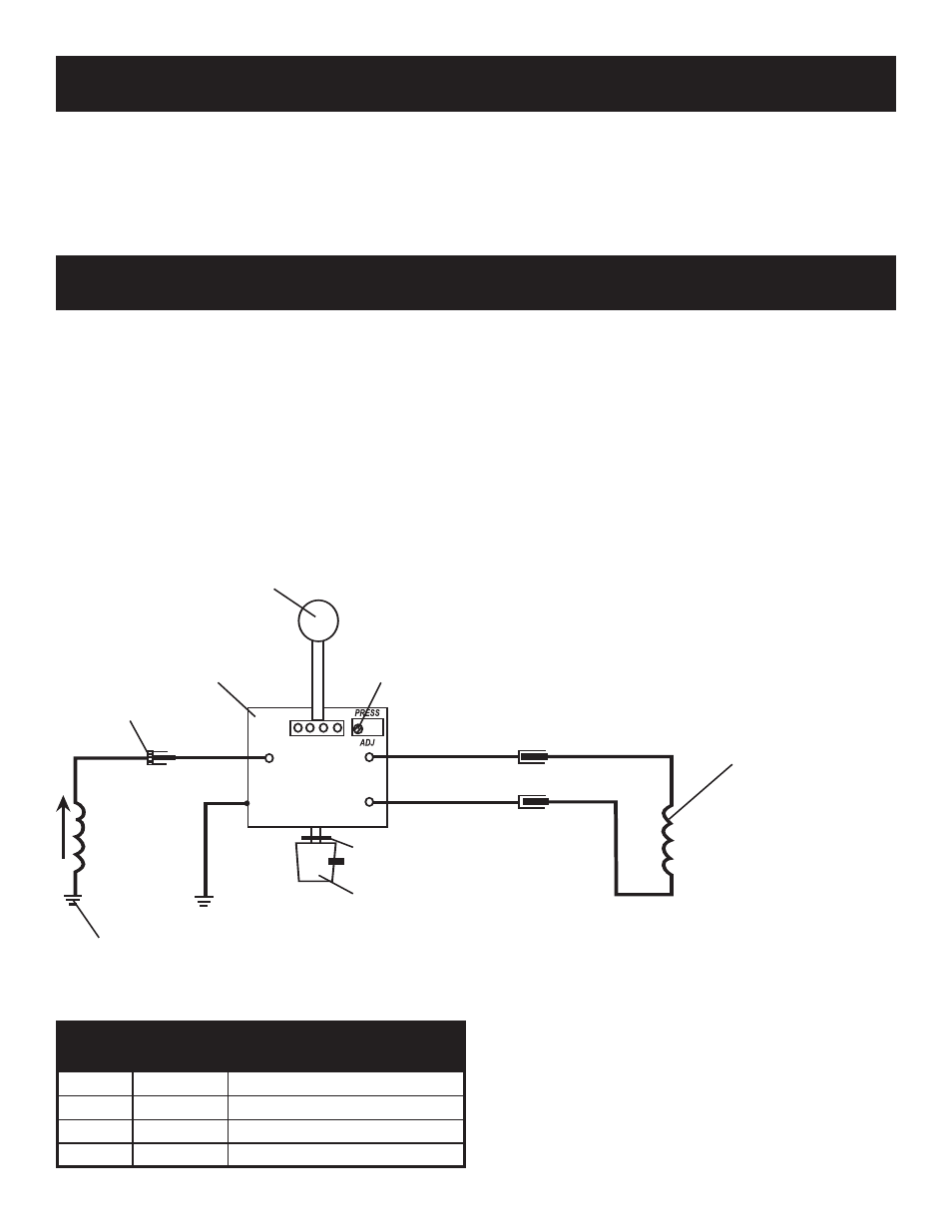
PARTS LIST FIGURE 26
Item No.
Part No.
Description
1
106-019
O-Ring
2
301-523A Knob
3
117-045
Grommet
4
301-282-99 Control Board
TO CLUTCH
(301-264)
2
PRESSURE
CALIBRATION
TRIMPOT
TO ENGINE
4
SENSOR
1
3
BLUE
BLUE
GREEN
BLACK
B
LA
C
K
BLACK
BLACK
FIG. 26