Testing the selected mounting location, Boat types, Establishing a performance baseline – Airmar 1 kW—M260 User Manual
Page 2: Testing the location
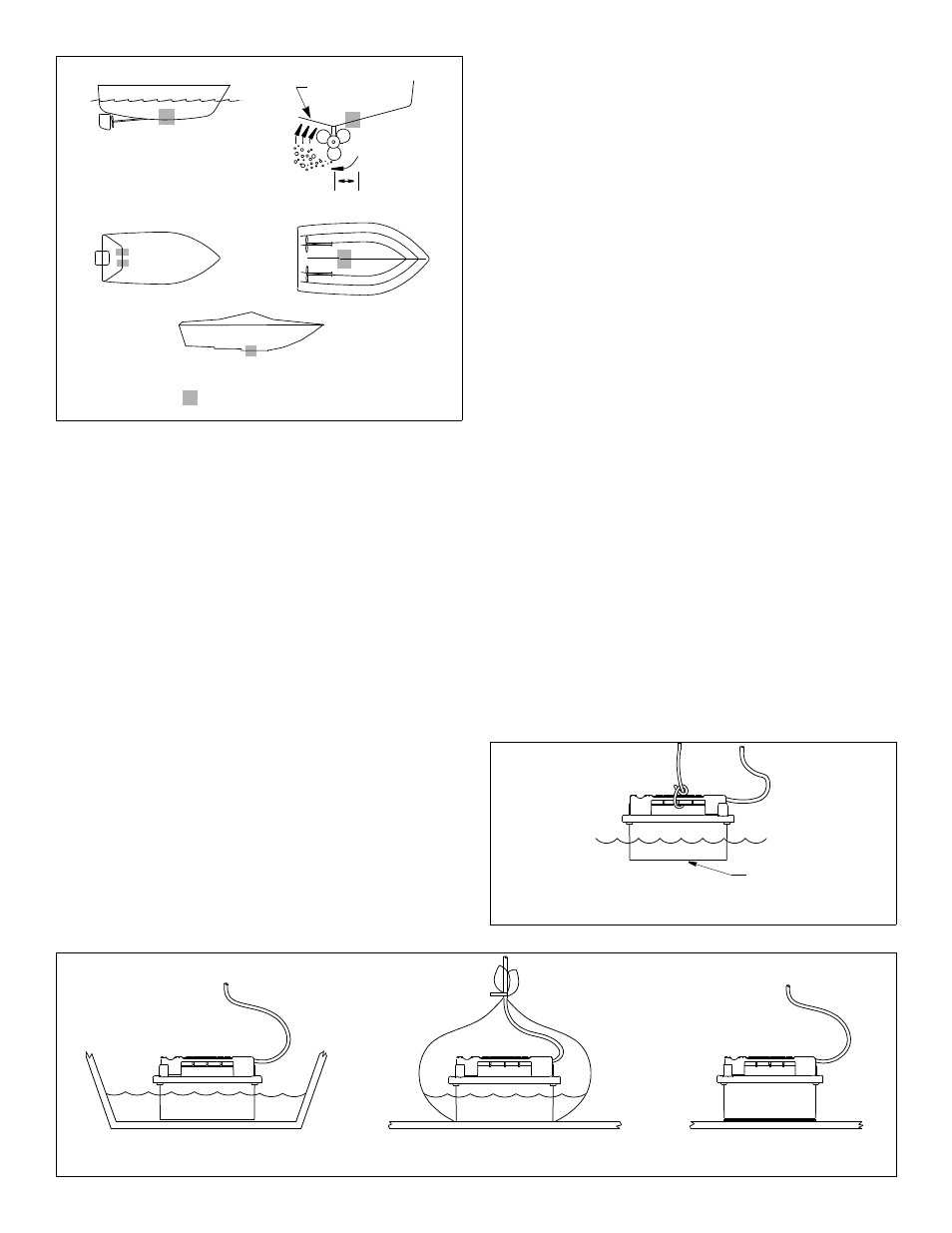
Boat Types
(see Figure 2)
• Displacement hull powerboats—Locate amidships near the
centerline. The starboard side of the hull where the propeller
blades are moving downward is preferred.
• Planing hull powerboats—Mount well aft, on or near the
centerline, and well inboard of the first set of lifting strakes to
ensure that the transducer will be in contact with the water at
high speeds. The starboard side of the hull where the propeller
blades are moving downward is preferred.
Outboard and I/O—Mount just forward of the engine(s).
Inboard—Mount well ahead of the propeller(s) and shaft(s).
Stepped hull—Mount just ahead of the first step.
Testing the Selected Mounting Location
Establishing a Performance Baseline
The results of this test are used as a basis of comparison to
determine the best in-hull location for the transducer.
1. Take the boat to the maximum depth in which you will be
operating the echosounder. If deep water is not available, find a
location with at least 30m (100').
2. Connect the transducer to the echosounder.
3. Tie a rope securely around the handle of the transducer (see
Figure 3). Lower it over the side of the boat until the active face
is fully submerged and parallel to the water surface.
4. Observe the echosounder’s performance and the depth reading.
Testing the Location
While the boat is at the same site (depth of water), test the
transducer inside the hull at the mounting location. Use one of the
test methods below:
A.If the transducer will be located near the stern and the boat has
a minimum deadrise angle—Clean away any build-up of dirt and/
or grease using detergent or a weak solvent such as alcohol. Place
the transducer against the hull and flood the area with bilge water
to cover the surface where they touch (see Figure 4-A).
B.For a moderate deadrise angle—If the hull surface is not
smooth, grind it with a disc sander. Place the transducer inside
a thin plastic bag. Partially fill the bag with water and close it
tightly with a cable tie. Wet the surface of the hull and press the
active face of the transducer against it through the bag (see
Figure 4-B).
C.For any location—If the hull surface is not smooth, grind it with a
disc sander. Coat the active face of the transducer with a water-
based lubricant (such as K-Y
®
jelly). With a twisting motion, press
the face firmly against the hull (see Figure 4-C). After testing,
wipe away all traces of the lubricant from the transducer’s face.
Observe the echosounder’s performance and compare it to the
baseline. Look for a stable depth reading that is similar to the
baseline. Compare the thickness and intensity of the bottom trace.
If the performance is close to the baseline, this is a good mounting
location. Remember, some energy is lost transmitting through the
hull. If the test reading differs markedly from the baseline, you will
need to find another location to install the transducer.
NOTE: If there is no reading or it is erratic, the transducer may be
positioned over coring which is absorbing the acoustic energy.
Choose another location. If no other location is available, check
with the boat manufacturer to be certain coring is present.
2
inboard
Figure 2.
pressure waves
displacement hull
(6-12")
150-300mm
Best location for the transducer
stepped hull
outboard and I/O
planing hulls
Copyright © 2006 Airmar Technology Corp.
Figure 4. Testing the transducer at the selected location
A
B
C
Copyright © 2006 Airmar Technology Corp.
Figure 3. Establishing a performance baseline
active face
Copyright © 2006 - 2011 Airmar Technology Corp.