Dvie22 – Archgard 27-DVIE22N User Manual
Page 39
27-DVIE22
39
1. Remove the surround.
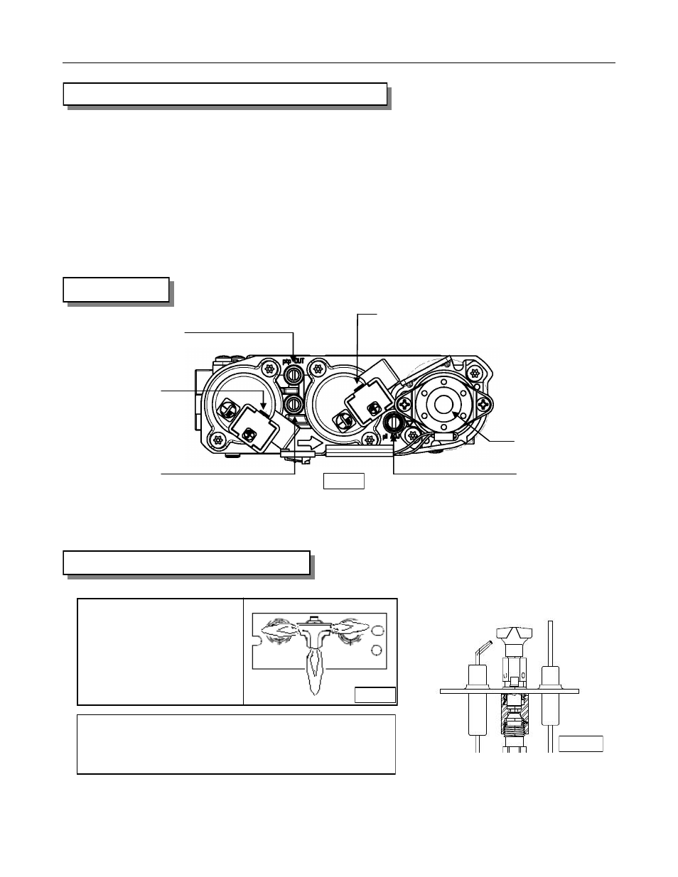
2. The pressure test taps are located on the valve. The taps are located in the gas valve front face.
The inlet is marked ‘IN’ and the outlet is marked ‘OUT’. See Fig.39-A
3. Loosen the set screw inside the tap with a screwdriver.
4. Connect a 1/4” (6 mm) rubber tube to the tap post and a manometer.
5. Verify that the readings obtained are within specs (as shown on the appliance rating plate)
6. Be sure to tighten the set screw inside the tap after you finish taking pressure readings.
7. Check for leaks.
CHECKING INLET AND OUTLET GAS PRESSURE
Outlet pressure tap
Stepper motor
Pilot connection
(orange)
Pilot flame adjustment
Inlet pressure tap
Main Valve Connection
(green)
GAS VALVE
CHECKING AND ADJUSTING PILOT
The flame should not have yellow tips but should engulf
the flame sensor and spark electrode. It can be adjusted
be turning the screw marked “pilot” on the control valve.
Sensor
Ignitor
The pilot flame should
have the characteristic as
shown in the illustration to
the right.
Fig. 39-A
Fig. 39-B
Fig. 39-C