H3C Technologies H3C S5120 Series Switches User Manual
Page 22
14
Grounding the switch with a grounding conductor buried in the
earth ground
If the installation site has no grounding strips, but earth ground is available, hammer a 0.5 m (1.64 ft) or
longer angle iron or steel tube into the earth ground to serve as a grounding conductor.
The angle iron must have a dimension no less than 50 × 50 × 5 mm (1.97 × 1.97 × 0.20 in) and the steel
tube must have a wall thickness no less than 3.5 mm (0.14 in) and be zinc-coated.
Weld the yellow-green grounding cable to the angel iron or steel tube and treat the joint for corrosion
protection.
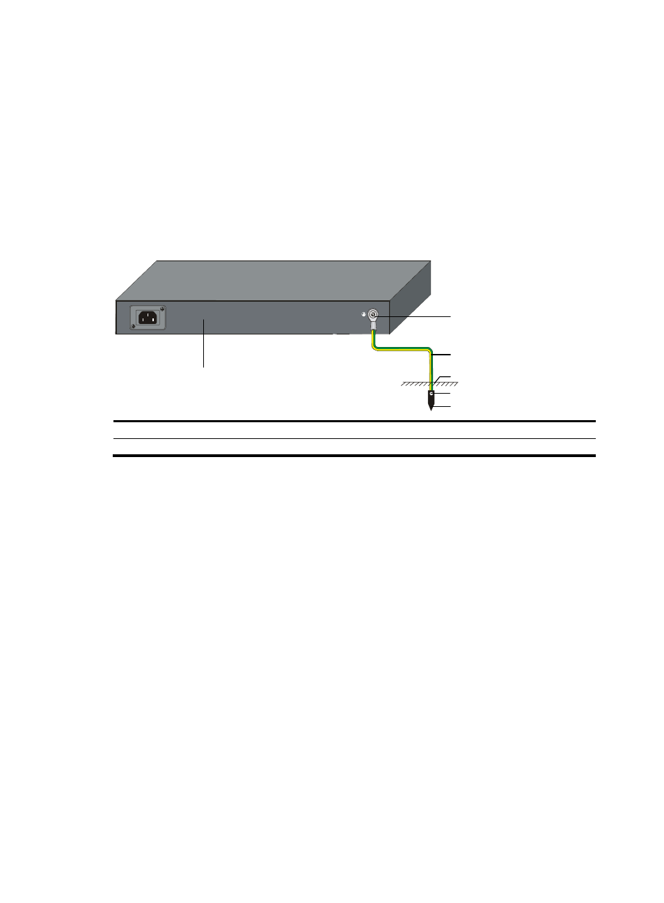
Figure 13 Grounding the switch by burying the grounding conductor into the earth ground
(1) Grounding screw
(2) Grounding cable
(3) Earth ground
(4) Joint
(5) Grounding conductor
(6) Switch rear panel
Grounding the switch in other grounding environments
If the installation site has no grounding strips or earth ground, you ground an AC-powered switch through
the PE wire of the AC power supply.
Make sure the PE wire is well connected to the ground at the power distribution room or AC transformer
side, the switch PE terminal and the PE wire are well connected, and the three-wire input cable of the
grounding cable is used for the power supply cable. If the PE wire of the AC power supply is not
grounded at the power distribution room or AC transformer side, report the problem and reconstruct the
grounding system.
(1)
(2)
(3)
(4)
(5)
(6)