Installing and removing an interface card, Installing an interface card, Figure – H3C Technologies H3C S5120 Series Switches User Manual
Page 26: Le (see callout 2 in, Figure 21
18
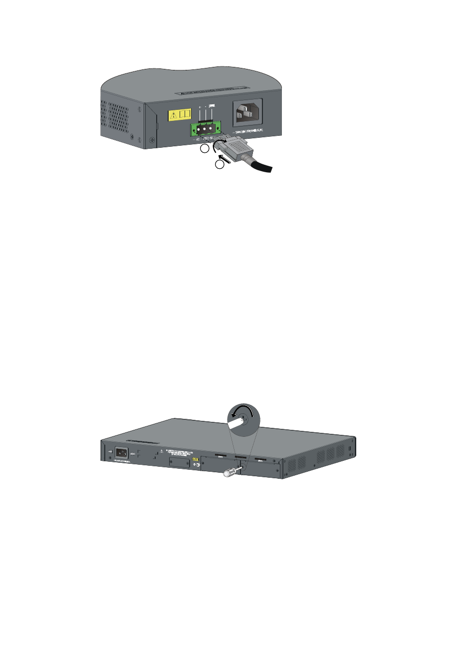
Figure 21 Connecting an RPS power cord to the S5120-28C-PWR-EI/S5120-52C-PWR-EI
4.
Connect the other end of the RPS DC power cord to the RPS power source.
5.
Verify that the RPS LED on the front panel of the switch is ON. If the LED is ON, it shows the power
cord is correctly connected.
Installing and removing an interface card
Each S5120-EI switch (except the S5120-24P-EI and S5120-48P-EI) provides two expansion slots on the
rear panel. For optional interface cards, see "
The installation and removal of various interface cards are similar. This section describes the installation
and removal of the 2-Port 10 GE SFP+ Interface Card (LSPM2SP2P) for illustration.
Installing an interface card
1.
Wear an ESD-preventive wrist strap, and make sure it makes good skin contact and is well
grounded.
2.
Loosen the mounting screws of the filler panel on the interface card slot of the switch's rear panel
with a Phillips screwdriver and remove the filler panel, as shown in
Figure 22 Installing an interface card (1)
3.
Hold the fastening screws on the front panel of the SFP+ interface card, and gently push the
interface card in along the slot guide rail until the interface card is in close contact with the switch,
as shown in callout 1 in
.
4.
Tighten the captive screws with a Phillips screwdriver to attach the interface card, as shown in
callout 2 in
1
2