S5120-52c-pwr-ei, Figure 46, Figure 47 – H3C Technologies H3C S5120 Series Switches User Manual
Page 46
38
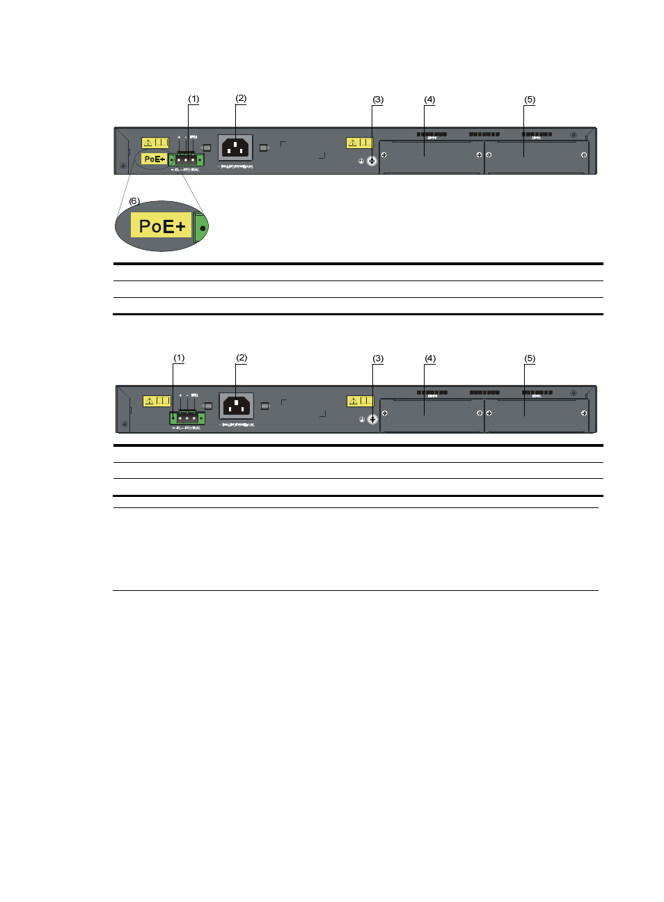
Figure 46 S5120-28C-PWR-EI (PoE+ model) fear panel
(1) RPS power input
(2) AC power input
(3) Grounding screw
(4) Interface card slot 1 (MOD1)
(5) Interface card slot 2 (MOD2)
(6) PoE+ label
Figure 47 S5120-28C-PWR-EI (PoE model) rear panel
(1) RPS power input
(2) AC power input
(3) Grounding screw
(4) Interface card slot 1 (MOD1)
(5) Interface card slot 2 (MOD2)
NOTE:
The S5120-28C-PWR-EI is shipped with the two expansion interface card slots covered by filler panels.
You can select one or two interface cards for your switch as needed. For the interface cards available for
the S5120-EI Switch Series, see "
." For how to install an interface card, see "
S5120-52C-PWR-EI
S5120-52C-PWR-EI includes two models: PoE and PoE+.
•
The front panels of the PoE and PoE+ models are the same in appearance. See
.
•
The PoE+ model has a PoE+ label on its rear panel, as shown in
. The maximum PoE power
per port is 30 W.
•
The PoE model has no PoE+ label on its rear panel, as shown in
. The maximum PoE power
per port is 15.4 W.
For more information about the PoE power supply, see
.