Connecting the rps power cord – H3C Technologies H3C S5120 Series Switches User Manual
Page 25
17
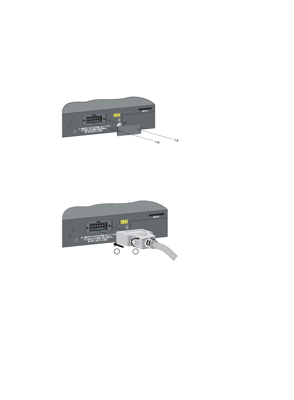
Connecting the RPS power cord
Connect RPS power cords of S5120-28C-EI, S5120-52C-EI, S5120-24P-EI, and S5120-48P-EI
1.
Wear an ESD-preventive wrist strap, and make sure it makes good skin contact and is well
grounded.
2.
Loosen the captive screws on the RPS receptacle protective cover and remove the protective cover,
as shown in
. (If you do not use the RPS interface, install the protective cover.)
Figure 19 Connecting an RPS power cord (1)
3.
Keep the upside of the RPS plug on top and plug it in the RPS DC receptacle (see callout 1 in
). (If you plug it with the upside down, the insertion is not smooth because of the specific
structure design of the RPS DC receptacle and the RPS plug.)
4.
Use a flat-blade screwdriver to attach the two screws on the RPS plug clockwise to secure the plug
to the RPS DC receptacle (see callout 2 in
).
Figure 20 Connecting an RPS power cord (2)
5.
Connect the other end of the +12 VDC RPS power cord to the RPS power source.
6.
Verify that the RPS LED on the front panel of the switch is ON. If yes, the power is correctly
connected.
Connecting the RPS power cord of the S5120-28C-PWR-EI and S5120-52C-PWR-EI
1.
Wear an ESD-preventive wrist strap, and make sure it makes good skin contact and is well
grounded.
2.
Keep the upside of the RPS plug on top and plug it in the RPS DC receptacle (see callout 1 in
). (If you plug it upside down, the insertion is not smooth because of the specific structure design
of the RPS DC receptacle and the RPS plug.)
3.
Use a flat-blade screwdriver to attach the two screws on the RPS plug clockwise to secure the plug
to the RPS DC receptacle (see callout 2 in
).
1
2