Connecting the grounding cable to the switch – H3C Technologies H3C S3100V2 Series Switches User Manual
Page 35
29
CAUTION:
•
The supplied grounding cable of the S3100V2 Switch Series does not have an auxiliary OT terminal.
•
Connect the grounding cable to the earthing system in the equipment room. Do not connect it to a fire
main or lightning rod.
Connecting the grounding cable to the switch
Follow these steps to connect the grounding cable to the switch:
Step1
Remove the grounding screw on the rear panel of the switch.
Step2
Attach the OT terminal on the grounding cable to the grounding screw on the chassis.
Step3
Fasten the grounding screw, which is attached with the OT terminal of the grounding cable, into the
grounding screw hole with a screwdriver.
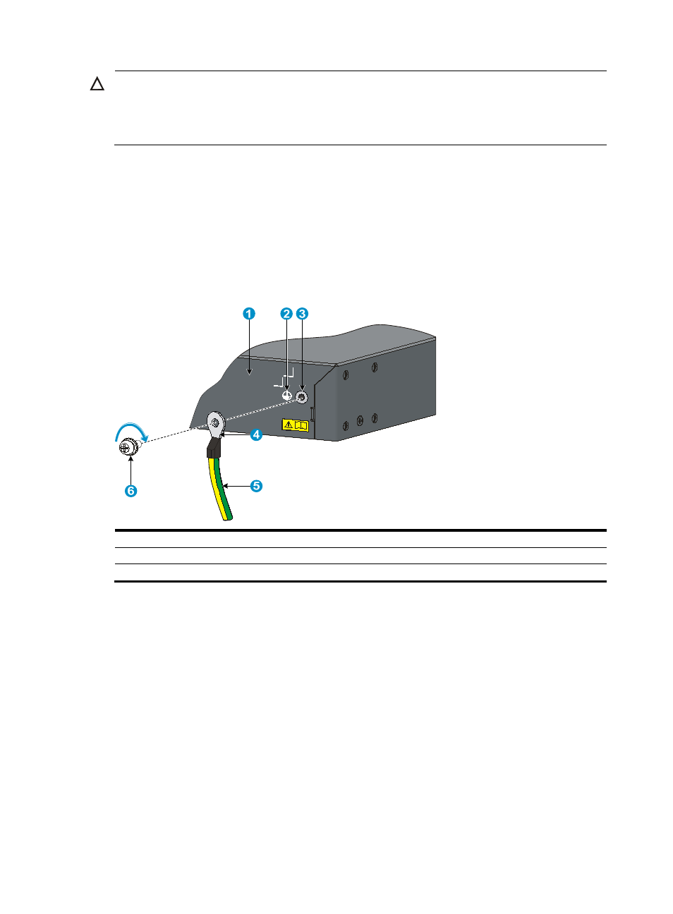
Figure 38 Connect the grounding cable to the switch
(1) Switch rear panel
(2) Grounding sign
(3) Grounding hole
(4) OT terminal
(5) grounding cable
(6) Grounding screw
Connecting the grounding cable to a grounding strip
Follow these steps to connect the grounding cable to a grounding strip:
Step1
Remove the hex nut from the grounding strip.
Step2
Cut the grounding cable to a proper length according to the distance between the switch and the
grounding strip.
Step3
Make the connector on the grounding cable:
•
If you have an OT terminal, follow callout A in
to make the connector: Peel 5 mm (0.20
in) of insulation sheath by using a wire stripper, and then insert the naked metal part through the
insulation covering into the end of the OT terminal. Secure the metal part of the cable to the OT
terminal with a crimper, and then cover it with the insulation covering. Then heat the insulation
covering with a blower to make it completely cover the metal part.
•
If you do not have an OT terminal, follow callout B in
to make the connector: Peel the
insulation sheath by an appropriate length by using a wire stripper, and then bend the naked metal