Verifying the installation, Figure – H3C Technologies H3C S3100V2 Series Switches User Manual
Page 40
34
Figure 46 DC power receptacle
+: Chassis ground
—: Input voltage range (–47 VDC to –57 VDC)
NULL: Reserved
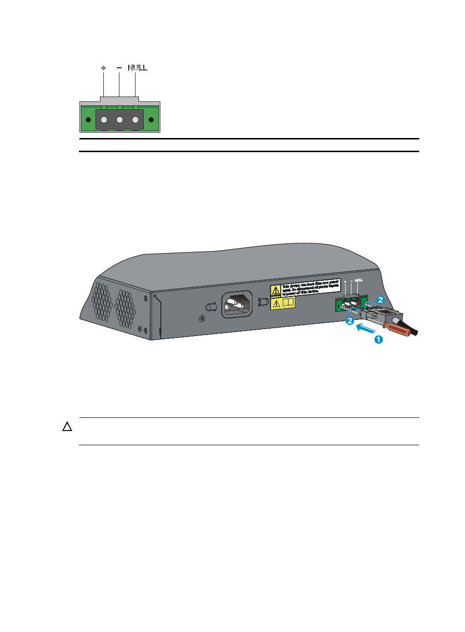
Follow these steps to connect the DC power cord:
Step1
Wear an ESD-preventive wrist strap and make sure it makes good skin contact and is well grounded.
Step2
Insert the power cord with the plug upside up. If you insert the power cord with the plug upside down,
you cannot insert the power cord smoothly because of its anti-reverse insertion structure. See callout 1 in
Figure 47 Connect the DC power cord
Step3
Fasten the screws on the power cord connector with a Phillips screwdriver to secure the power cord
connector to the DC power receptacle, as shown in callout 2 in
Step4
Connect the other end of the DC power cord to the DC power source.
Step5
Check the power LED (PWR) on the front panel. If the LED is on, the power cord is properly connected.
CAUTION:
The length of a DC power cord must be shorter than 3 m (9.84 ft).
Verifying the installation
Verify the following items after the installation:
•
There is enough space for heat dissipation around the switch, and the rack or workbench is stable.
•
The grounding cable is connected.
•
The selected power supply matches that required by the switch.
•
The power cords are properly connected.