Network requirements, Vrrp interface tracking configuration example – H3C Technologies H3C MSR 50 User Manual
Page 89
81
# After Router A resumes normal operation, use the display vrrp verbose command to display the
detailed information about VRRP group 1 on Router A.
[RouterA-Ethernet1/1] display vrrp verbose
IPv4 Standby Information:
Run Mode : Standard
Run Method : Virtual MAC
Total number of virtual routers : 1
Interface Ethernet1/1
VRID : 1 Adver Timer : 1
Admin Status : Up State : Master
Config Pri : 110 Running Pri : 110
Preempt Mode : Yes Delay Time : 5
Auth Type : None
Virtual IP : 202.38.160.111
Virtual MAC : 0000-5e00-0101
Master IP : 202.38.160.1
The output shows that after Router A resumes normal operation, it becomes the master, and
packets sent from Host A to Host B are forwarded by Router A.
VRRP interface tracking configuration example
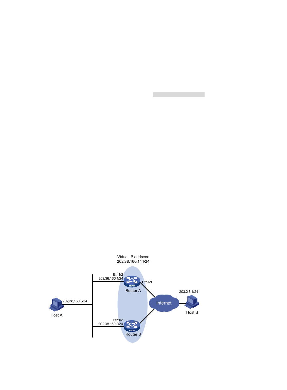
Network requirements
•
Host A wants to access Host B on the Internet, using 202.38.160.111/24 as its default gateway.
•
Router A and Router B belong to VRRP group 1 with the virtual IP address of 202.38.160.111/24.
•
When Router A operates correctly, packets sent from Host A to Host B are forwarded by Router A.
When interface Ethernet 1/1 through which Router A connects to the Internet is not available,
packets sent from Host A to Host B are forwarded by Router B.
•
To prevent attacks to the VRRP group from illegal users by using spoofed packets, configure the
authentication mode as plain text to authenticate the VRRP packets in VRRP group 1. Specify the
authentication key as hello.
Figure 29 Network diagram