Grass Valley ADC-1101 User Manual
Page 9
GUIDE TO INSTALLATION AND OPERATION
ADC-1101 | 5
3.2.1 Status
LED
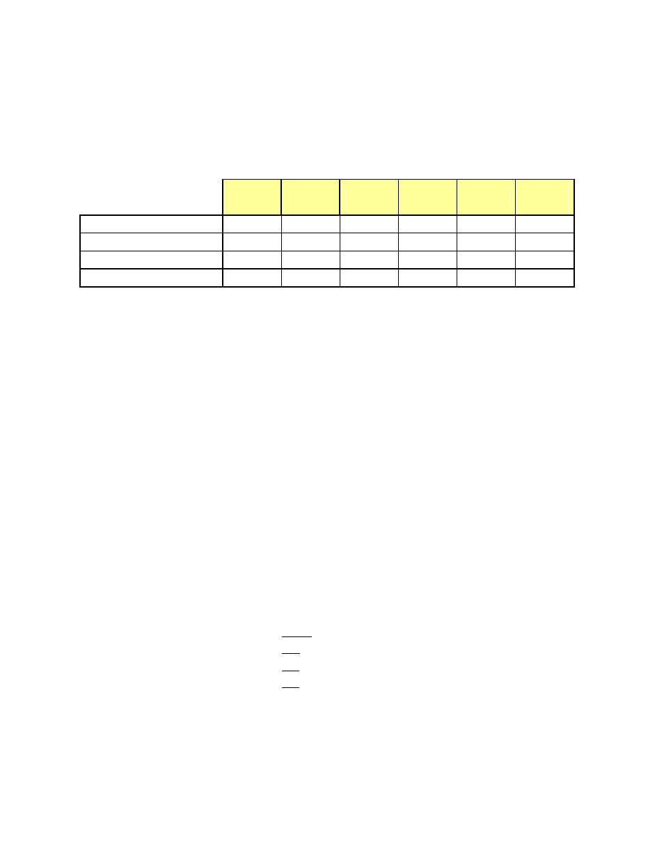
The status monitor LED is located on the front card-edge of the ADC-1101, and is visible through the front
access door of the DENSITÉ frame. This multi-color LED indicates module status by color, and by
flashing/steady illumination, according to the chart. The chart also indicates fault reporting for this card on the
DENSITÉ frame’s serial and GPI interfaces.
Serial
Report
GPI
Report
Green
Yellow
Red
Flashing
Red
No input signal presence
Input
Format
Error
Test
Card System
: Factory default.
NOTE: A “Flashing Yellow” Status LED indicates that the SELECT button on the front panel has been
pushed.
3.2.2 Menu for local control
The ADC-1101 has operating parameters which may be adjusted locally at the controller card interface. After
pressing the SELECT button on the ADC-1101 module, use the keys on the local control panel (described
above) to step through the displayed menu and adjust the parameters. The menu is shown below.
STATUS
NO SIGNAL / 525 / 625
NO REAR / SINGLE REAR
TEST
ON
A1
MISSING
A2
MISSING
HARDWARE
FAILURE
INPUT FORMAT
[SMPTE / GBR / GBR w. setup / BETA / BETA w. setup]
(525)
[EBU / GBR / BETA]
(625)
CC
[OFF, ON]
(525)
WSS
[OFF, ON]
(625)
AUTO CALIBRATE
START
O.K / NO GOOD
USER PRESET
LOAD
[USER 1 ,USER 2, USER 3, USER 4, USER 5]
SAVE
[USER 1 ,USER 2, USER 3, USER 4, USER 5]