Video cabling – Grass Valley Kalypso Emergency Bypass Option User Manual
Page 18
18
Kalypso Emergency Bypass Option Instruction Manual
Installation
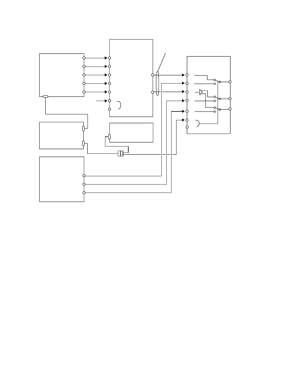
Figure 8. Emergency Bypass Cabling
Video Cabling
Note
Label templates are provided (BYPASS KEYER and BYPASS RELAY) that can
be placed over the BNC connectors on the rear of the Emergency Bypass
frame. These templates identify the signals for each module.
Refer to
Figure 8
.
•
Connect the Router destinations for Key Cut, Key Fill, and Background
signals to the Bypass Keyer Module, using the J connector numbers
shown in the figure. Alternatively, the Key Cut and Fill signals can
come from an external device, but then these signals cannot be
switched from the Kalypso Local Aux panel.
•
Connect the Program 1 Output from the Kalypso Video Processor
frame to the Relay Module, as shown. You can also connect another
Program output and a Preview output if you wish.
•
Connect the J1 output (Program) from the Keyer Module to the J4 input
of the Relay Module, and the J2 output (Preview) to the J3 input.
Use DAs here if monitoring
or multiple Relay Modules
are required.
0721_07_62_r3
J3
J1
J4
J5
J7
J2
J6
J8
Pvw Out
Pgm 1 Out
Pgm 2 Out
Do
Not
Terminate
Bypass Relay Module
8900TF Frame Cell 7
Bypass Keyer Module
8900TF Frame Cell 8
Bypass Monitor Module
8900TF Frame Cell 11
Looping
Reference
Input
J3
J4
J5
J6
Key Cut 1
Key Cut 2
Key Fill 1
PVW
Pgm 1
Pgm 2
Key Fill 2
J7
Background
Pvw J2
Pgm J1
SMS 7000
Router
Analog 525/625
Reference
Breakout Cable
Kalypso
Video
Processor
Frame
Kalypso
Local
Aux Panel
Emg Bypass
Router
Emg Bypass
Mixer
RS-422
RS-422
J9
J10
J102
Terminate
or Loop
J9
J10