Continuity control, Figure 100 – Grass Valley Kalypso User Manual V.15.0 User Manual
Page 120
120
Kalypso — User Manual
Section 2 — Concepts
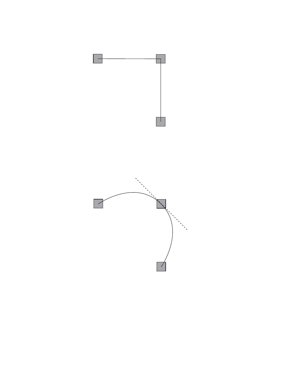
Figure 100. Tension Control Setting 1.0
In the example below, the
TENSION
control has been set to -1.0. This
lengthens the Tension vector, causing the path through the middle key-
frame to be longer and broader (
). The longer path will appear to
make the image speed up through KF2 as it travels from KF1 to KF3.
Figure 101. Tension Control Setting -1.0
Continuity Control
The continuity adjustment determines the angle of the path into and out of
the keyframe. It is represented by a vector 90 degrees to the tension vector
(
). The unmodified path shown is identical to the unmodified
path of the other controls.
Tension = 1.0
KF1
KF2
KF3
No Tension Vector
0721_06_48_r0
Tension = -1.0
KF1
KF2
KF3
Tension
Vector
0721_06_49_r0