Main input circuit and motor wiring – Yaskawa AC Drive Z1000 Bypass Technical Manual User Manual
Page 63
Z1000 Bypass
Model Z1B1
With Option PM Circuit Breaker CB1
Standard Non-Fused Input Disconnect Switch S1
208
Vac
480
Vac
Current Rating
(A)
Wire Size Range
(AWG)
Tightening
Torque (lb. in.)
Current Rating
(A)
Wire Size Range
(AWG)
Tightening
Torque (lb. in.)
D211
–
400
(1-2) x
(2/0-500 kcmil)
(1-2) x 442
400
(1-2) x
(2/0-500 kcmil)
(1-2) x 442
D273
B240
600
(1-2) x
(2/0-500 kcmil)
(1-2) x 442
–
B302
600
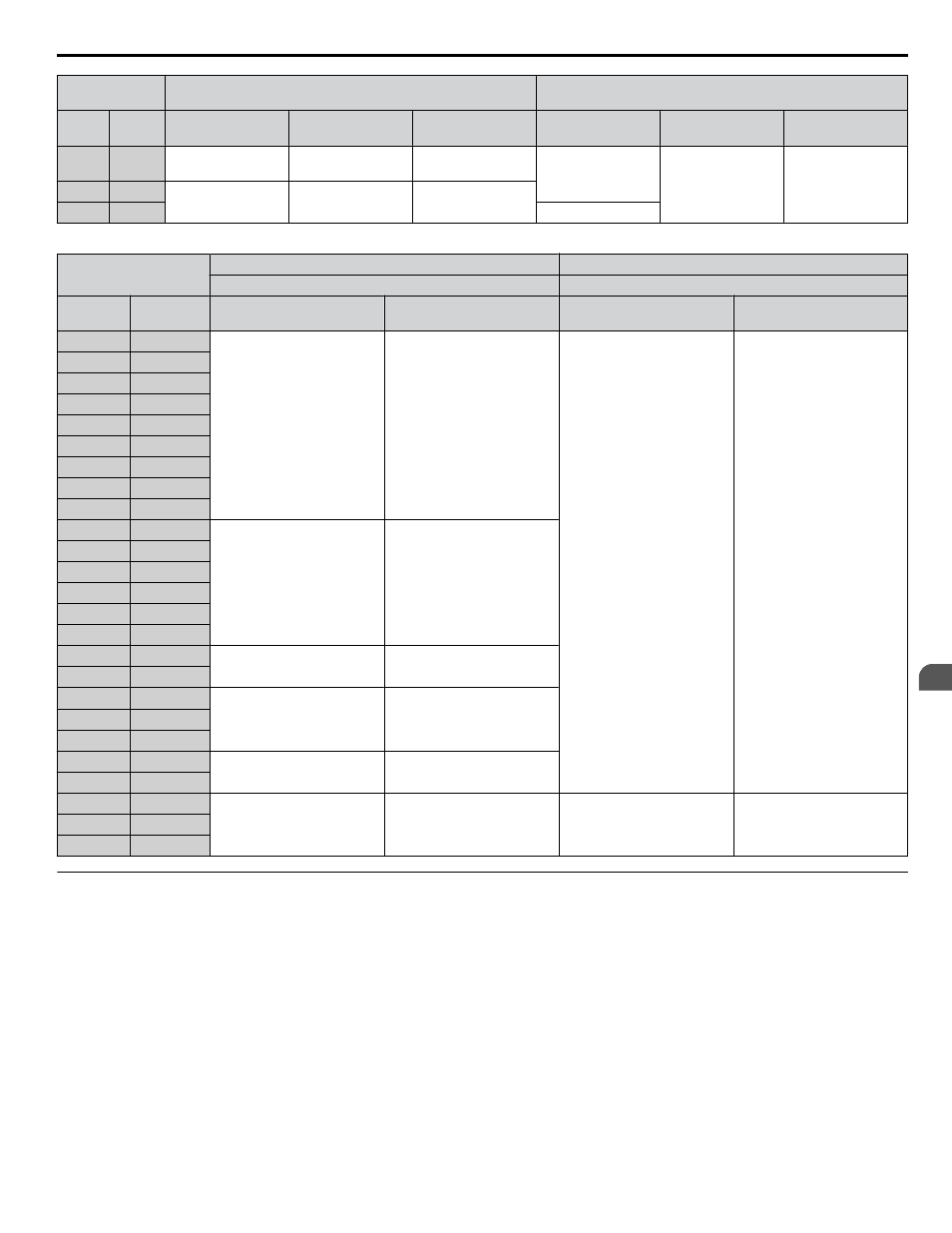
Table 3.3 Motor and Ground Wire Gauges and Tightening Torques
Z1000 Bypass
Model Z1B1
Output Circuit Motor Wiring
Earth Ground Wiring
Motor Overload Relay
Ground Lug
208 Vac
480 Vac
Wire Size Range (AWG)
Tightening Torque
(lb. in.)
Wire Size Range (AWG)
Tightening Torque
(lb. in.)
–
B001
18-8
15
14-10 or 8 or 6-4 or 2
35 or 40 or 45 or 50
D002
B002
D003
B003
D004
B004
D007
B007
D010
B011
D016
B014
D024
B021
D030
B027
–
B034
16-2
70
–
B040
–
B52L
D046
–
D059
–
–
B052
D074
B065
10-1/0
100
–
B077
D088
B096
6-3/0
200
D114
B124
D143
–
D169
B156
6-300 kcmil
275
–
B180
D211
B240
(1-2) x (2/0-600 kcmil)
(1-2) x 500
14-2/0
120
D273
–
–
B302
u
Main Input Circuit and Motor Wiring
This section outlines the various steps, precautions, and checkpoints for wiring the main circuit terminals and motor terminals.
WARNING! Electrical Shock Hazard. Do not connect the AC power line to the bypass output terminals. Failure to comply could result in
death or serious injury by fire as a result of bypass damage from line voltage application to output terminals.
NOTICE: Route motor leads U/T1, V/T2, and W/T3 separate from all other leads to reduce possible interference related issues. Failure to
comply may result in abnormal operation of drive and nearby equipment.
NOTICE: When connecting the motor to the output terminals T1, T2, and T3, the phase order for the drive and motor should match. Failure
to comply with proper wiring practices may cause the motor to run in reverse if the phase order is backward.
NOTICE: Do not connect phase-advancing capacitors or LC/RC noise filters to the output circuits. Failure to comply could result in damage
to the drive, phase-advancing capacitors, LC/RC noise filters or ground fault circuit interrupters.
3.4 Input and Output Power Wiring Connections
YASKAWA ELECTRIC SIEP YAIZ1B 01D YASKAWA AC Drive – Z1000 Bypass Technical Manual
63
3
Electrical Installation