Chapter 3: board layout, External connectors, Chapter 3 – Lanner LEC-7950 User Manual
Page 10: Board layout
Advertising
9
Board Layout
Chapter 3
Embedded and Industrial Computing
Chapter 3:
Board Layout
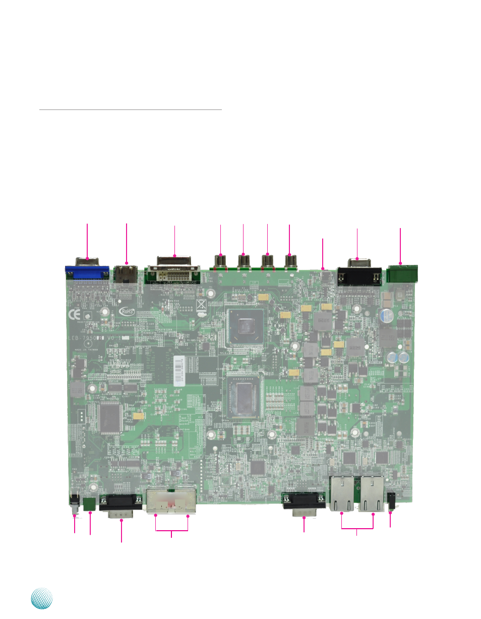
External Connectors
The following picture highlights the location of system
input/output connectors. Refer to the table 3.2 Connector
List for more details.
J5
J4
J3
J2
dVId1
HdMI1
VGA1
PBT1 J1
CN3
UsB1/UsB2
CN4
LAN1/LAN2
LEd1
CN2
CN1
RsT1
Advertising