Chapter 3, Board layout – Lanner LEC-7950 User Manual
Page 14
13
Board Layout
Chapter 3
Embedded and Industrial Computing
Switch
Protocol
J10
SC2T1
RS-232 (default)
1-2,
1-5, 2-6, 3-7, 4-8
RS-422
3-4, 5-6
5-9, 6-10, 7-11, 8-12
RS-485
3-4, 7-8
5-9, 6-10
J14, SC2T2: Select COM2 Protocol Setting
RS-232
RS-422
RS-485
Switch
Protocol
SCT3
SCT4
RS-232 (default)
1-2
1-5, 2-6, 3-7, 4-8
RS-422
3-4, 5-6
5-9, 6-10, 7-11, 8-12
RS-485
3-4, 7-8
5-9, 6-10
J11, J9: Select Termination in RS-485 for COM1 and COM2
respectively. We strongly recommend that you disable
termination when the port is configured as RS-232 and
enable it when the port is configured as RS-485/RS-422.
Pin No.
Function
1-2, 3-4, 5-6, 7-8
Termination TX, RX
on
Termination off
J12, J13 : Select COM1 and COM2 Pin No9 (Ring Indicator)
function respectively
JP1
Pin
Signal
1-2
RI
3-4
5V
5-6
12V
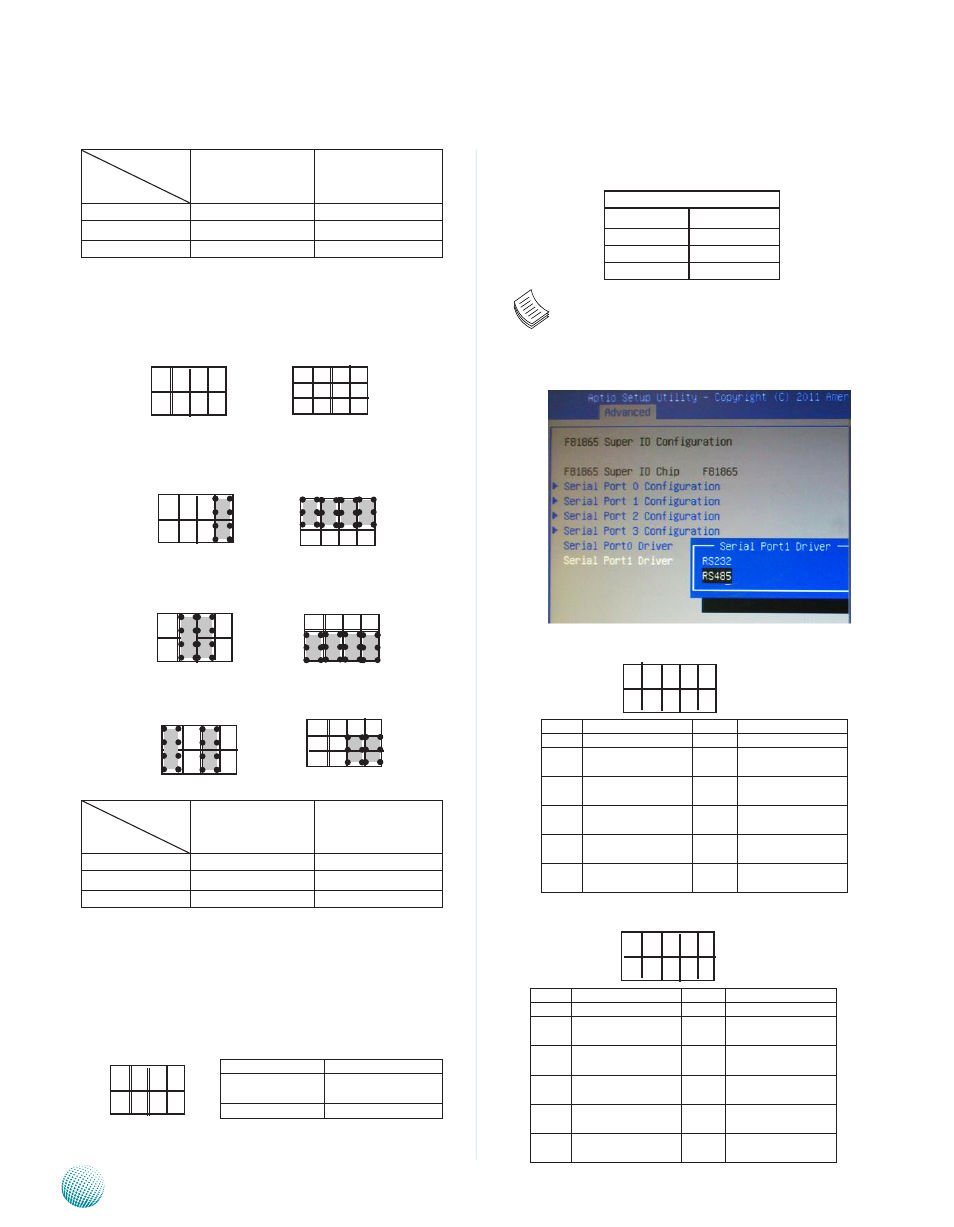
Note: Besides jumper settings, you should also
select the communication protocol in the BIOS as
shown in the following picture, select Advanced
->F81865 SuperIO Configuration->Serial Port 0/1
Driver->RS232 or RS485
COM3 RS-232 Serial Port (J8)
COM4 RS-232 Serial Port (J7)
SC2T2
4
8
12
1
5
9
1
2
7
8
J14
1
2
7
8
J9 (COM2), J11(COM1)
Pin No.
Pin Name
Pin No.
Pin Name
Rs-232
1
data Carrier detect
(dCdA # )
6
Clear to send
(CTs)
2
data set Ready
(dsRA # )
7
data Terminal Ready
(dTR )
3
Receive data
(RXd)
8
Ring Indicator
(RI)
4
Request to send
(RTs )
9
GNd
5
Transmit data
(TXd)
1
2
9
10
1
2
9
10
Pin No.
Pin Name
Pin No.
Pin Name
Rs-232
1
data Carrier detect
(dCdA # )
6
Clear to send
(CTs)
2
data set Ready
(dsRA # )
7
data Terminal Ready
(dTR )
3
Receive data
(RXd)
8
Ring Indicator
(RI)
4
Request to send
(RTs )
9
GNd
5
Transmit data
(TXd)