Rear components, Chapter 2, System components – Lanner LEC-7950 User Manual
Page 9
8
System Components
Chapter 2
Embedded and Industrial Computing
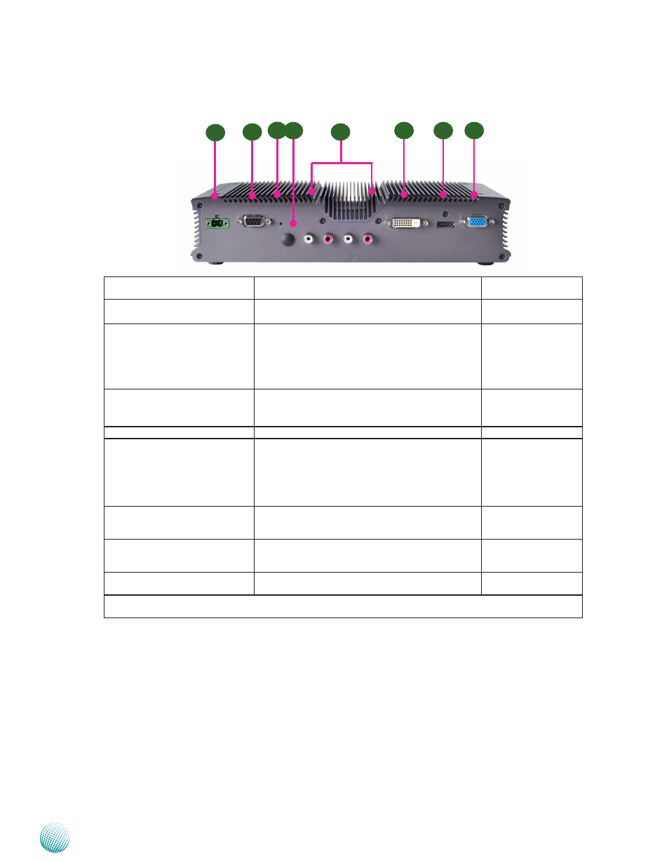
Rear Components
R2
R1
R5
Component
Description
Pin Definition
Reference
F1 DC-In (power) 1x2 Pin Phoenix
Contact Connector
Power-in Connector. The LEC-7950 supports power
input of +24V DC-in.
CN1 on page 15
F2 DIO Port
The general-purpose input/output1 (GPIO)
peripheral provides dedicated general-purpose
pins. The digital input helps triggering between
open and closed circuit such as PIRs, door/window
contact, glass break detector. And the output can
connect to devices such as relays and LEDs.
CN2 on page 15
F3 Reset Switch
A hardware reset switch. Use a pointed object to
press it 5 seconds then release it to reset the system
without turning off the power.
RST1 on page 15
F4 Antenna Hole
Reserved for antenna
F5 Line_Out_L
Line_Out_R
Line_in_L
Line_in_R
RCA Jack for audio output and input
J2, J3, J4, J5 on page
12
F6 DVI-D (*)
A DVI-D port (single link) which is provided by
Intel HD Graphic Engine. This port can support up
to 1920x1200 @ 60 Hz resolution.
DVID1 on page 15
F7 HDMI (*)
The HDMI (High-Definition Multimedia Interface).
This port can support up to 1920x1200 @ 60 Hz
resolution.
HDMI1 on page 15
F8 VGA Port (*)
The displays can support VGA up to 2048x1536
resolution.
VGA1 on page 15
* The system cannot support all three display methods at the same time. It can only support two of them
simultaneously.
R6
R7
R8
R3 R4