Magnum Energy MP Extension Box (MPX Series) User Manual
Page 15
3.0 Installation
© 2011 Magnum Energy, Inc.
11
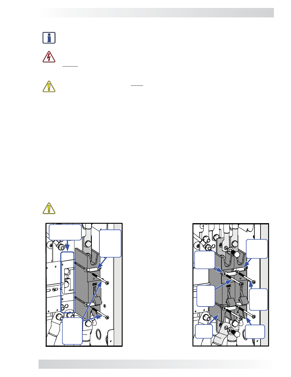
Fig. 3-7, Removing Breaker Screws
Fig. 3-8, Attaching the New DC Breaker
3.1.4 Attaching the DC and AC Breakers
Info: The holes on the breaker mounting plate inside the MP enclosure — for Torx screws
that hold the new DC and AC breakers — are NOT pre-threaded. Use a power driver to
screw these self-threading screws into the mounting plate.
WARNING:
During normal operation the terminals, busbars, and electrical components
inside the MP enclosure may be energized - DO NOT TOUCH. Disconnect all power sources
before removing the cover.
DC Breaker
CAUTION:
The DC breakers must be mounted in a vertical position to meet the specifi ed
trip current and trip delay curve.
The DC breaker is attached within the MP enclosure and functions as the inverter’s DC disconnect switch.
The DC breaker can be used as the battery-to-inverter circuit protection in most installations.
1. Using a T25 screwdriver, remove two of the #10-32 x 3½” Torx screws that secure the existing
DC breaker to the mounting plate – the removed screws should be the two that are adjacent to
where the new DC breaker will be mounted (see Figure 3-7).
2. Place the new DC breaker against the MP’s mounting plate and next to the existing DC breaker
where the two mounting straps are loose.
3. While holding the new DC breaker in place, fi t two new mounting straps over the new DC breaker.
Ensure the holes on the new mounting straps — that are over the new DC breaker — line up with
the holes of the adjacent two existing mounting straps (see Figure 3-8).
4. Insert the two Torx screws that were removed in Step 1 into the aligned holes of the new and
existing mounting straps on the adjacent sides of the breakers, and then tighten to secure the
existing DC breaker. Insert two new #10-32 x 3½” Torx screws into the other side of the new
mounting straps and tighten enough to hold the new DC breaker in place. Do not fully tighten the
screws, that will be done in Step 5 after being aligned.
5. Check for proper breaker alignment by temporarily placing the MP’s front panel cover over the DC
breakers. If fi t and alignment are correct, tighten all Torx screws to secure the new DC breaker.
CAUTION:
Be careful not to over-tighten to the point of bending down the tabs on the
mounting straps.
Leave
existing
mounting
straps
(x2)
in place
Mounting Plate
(location for
new breaker)
Remove
screws
adjacent
to new
breaker
location
New
mounting
straps
(x2)
Existing
mounting
straps
(x2)
Existing
torx
screws
(x2)
Existing
DC
breaker
New
DC
breaker
New
torx
screws
(x2)
Note: Figure 3-8 in-
cludes the new break-
er’s DC wire connec-
tions. Actual connec-
tions occur in Section
3.2.